Transmission mechanism used for reciprocating compressor

A transmission mechanism and compressor technology, applied in the field of mechanical transmission, can solve the problems of multi-structure and complexity of moving parts, increase the actual production cost of the machine body, etc.

Inactive Publication Date: 2014-05-21
HEFEI GENERAL MACHINERY RES INST
View PDF7 Cites 2 Cited by
  • Summary
  • Abstract
  • Description
  • Claims
  • Application Information

AI Technical Summary

Problems solved by technology

However, due to the relationship between its own design principles, there are still many problems, especially the defects of too many moving parts and too complicated structure, which have not been overcome by research so far; On the one hand, when the eccentric wheel drives the connecting rod to move, the large swing of the connecting rod will inevitably require a large range of movement space, which is even more limited in the internal volume of the relatively precious compressor; on the other hand, the connecting rod and the piston The ring sleeve fit between them will not only lead to inevitable friction and wear on the matching parts after long-term use, which will lead to the reduction of its overall service life and the complexity of maintenance. At the same time, the hollow ring sleeve design structure of the piston, It also puts forward strict requirements on the design strength of the piston itself, so it has to be made of more expensive materials, which greatly increases the actual production cost of the entire body

Method used


Image

  • Transmission mechanism used for reciprocating compressor
  • Transmission mechanism used for reciprocating compressor
  • Transmission mechanism used for reciprocating compressor

Examples


Embodiment Construction

[0024] For ease of understanding, here in conjunction with accompanying drawing, specific testing device of the present invention and its operation process are further described as follows:

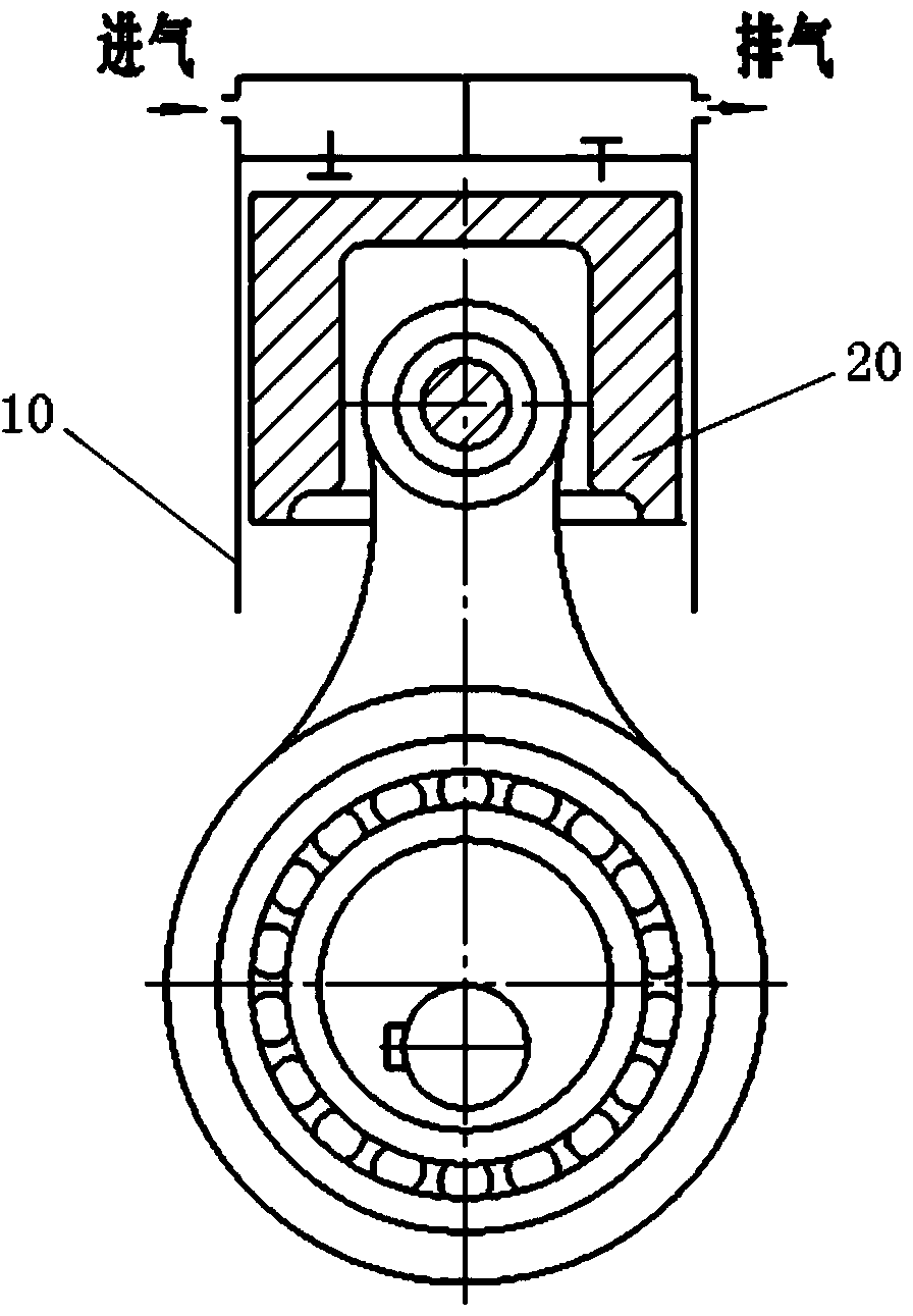
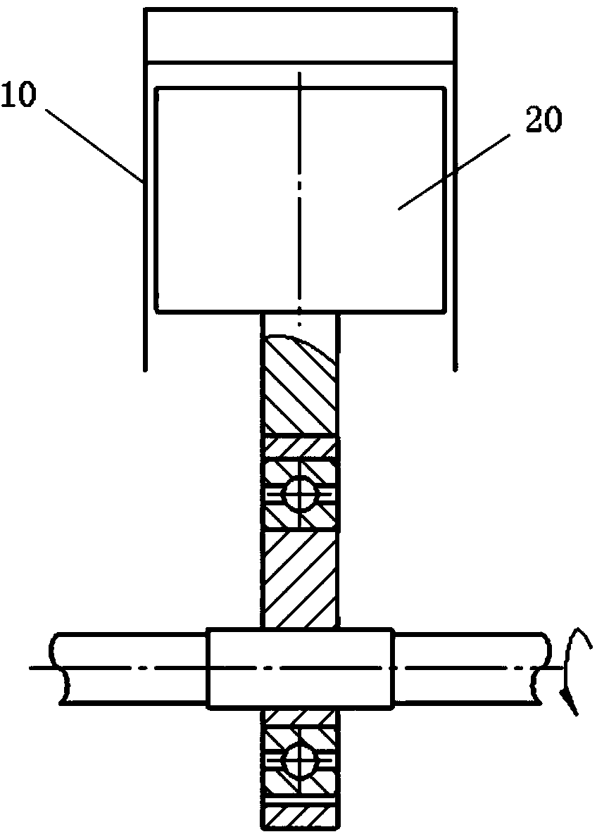
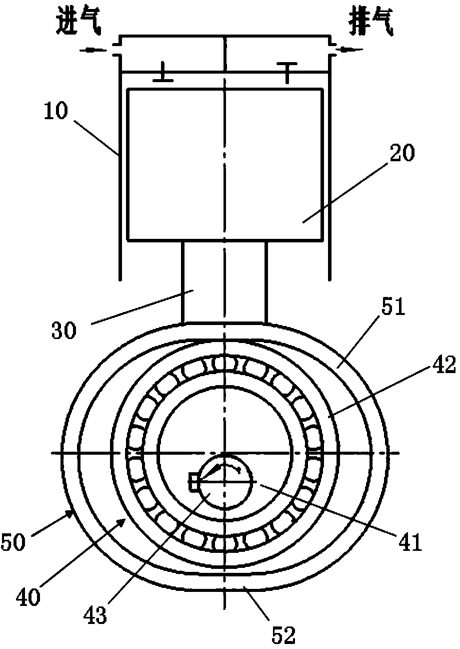
[0025] Such as Figure 3-6 As shown, the present invention transmits power through the transmission yoke 50, and the piston 20, the connecting rod 30 and the transmission yoke 50 are fixedly connected among the three; of course, the above three can also be made into an integrated connection structure, and its structure is obviously compared with The existing hinge structure is simpler and easier to implement, and can fundamentally eliminate the friction and wear between the connecting rod and the piston; in addition, during operation, the rolling bearing in the eccentric part 40 only needs to meet the requirements of continuous movement in the transmission yoke 50. The power can be transmitted by rolling, and the axial installation between the rolling bearing and the transmission yoke 50 ...


PUM


Abstract

The invention relates to the field of mechanical transmission, in particular to a transmission mechanism used for a reciprocating compressor. The transmission mechanism comprises a piston which is connected to the inside of a cylinder in an inserted mode and can move in a reciprocating mode in the axis direction of the cylinder. The transmission mechanism further comprises a connecting rod and an eccentric portion used for a drive element, wherein the eccentric portion, the connecting rod and the piston form crank block matching, the end, matched with the eccentric portion, of the connecting rod is provided with a transmission yoke attached to the outer edge of the eccentric portion, the transmission yoke at least comprises two yoke edges which are sequentially arranged from top to bottom in the axis direction of the piston, the eccentric portion rotates in the area between the two yoke edges so as to abut against the inner surfaces of the yoke edges and drive the piston to move in a reciprocating mode, and when the piston moves in a reciprocating mode, the inner surfaces of the two yoke edges are in line contact matching with the outer edge of the eccentric portion in turn. The transmission mechanism is long in service life and simple in structure and can solve the problem that due to the fact that matching portions of components are multiple, maintenance is frequently carried out.

Description

technical field [0001] The invention relates to the field of mechanical transmission, in particular to a transmission mechanism for a reciprocating compressor. Background technique [0002] The reciprocating compressor belongs to the volumetric compressor, which is a compression machine that sequentially sucks and discharges a certain volume of gas into and out of a closed space to increase the static pressure. The main mechanism of the current reciprocating compressor is usually as figure 1 As shown, it consists of a cylinder 10, a piston 20 sleeved in the cylinder 10, and an eccentric wheel located at the opening side of the cylinder 10. The outer edge of the eccentric wheel is concentrically arranged with an outer ring, and the outer ring is formed by its ring body extending toward the piston 20. The piston rod that fits with the ring sleeve; in actual work, the eccentric wheel rotates to drive the outer ring to move, and the outer ring then transmits the torque to the p...

Claims


Application Information

Patent Timeline
Patent Type & Authority Applications(China)
IPC IPC(8): F04B39/00
Inventor 张成彦薛卫东鲍军刘岑于洋王树胜
Owner HEFEI GENERAL MACHINERY RES INST
Why Eureka
Try Eureka