Underwater cast-in-situ bored pile reverse circulation efficient hole-forming construction device and method

A technology of bored cast-in-place piles and construction methods, which are applied to underwater drilling, drilling tools, sheet pile walls, etc., can solve the problems of low efficiency of bored cast-in-place piles in water, etc.

Pending Publication Date: 2021-10-01
衡阳公路桥梁建设有限公司
View PDF4 Cites 1 Cited by
  • Summary
  • Abstract
  • Description
  • Claims
  • Application Information

AI Technical Summary

Problems solved by technology

[0004] In order to improve the low efficiency of bored piles in water, this application provides a reverse circulation and high-efficiency hole-forming construction device and method for bored piles in water

Method used


Image

  • Underwater cast-in-situ bored pile reverse circulation efficient hole-forming construction device and method
  • Underwater cast-in-situ bored pile reverse circulation efficient hole-forming construction device and method
  • Underwater cast-in-situ bored pile reverse circulation efficient hole-forming construction device and method

Examples


Embodiment 1

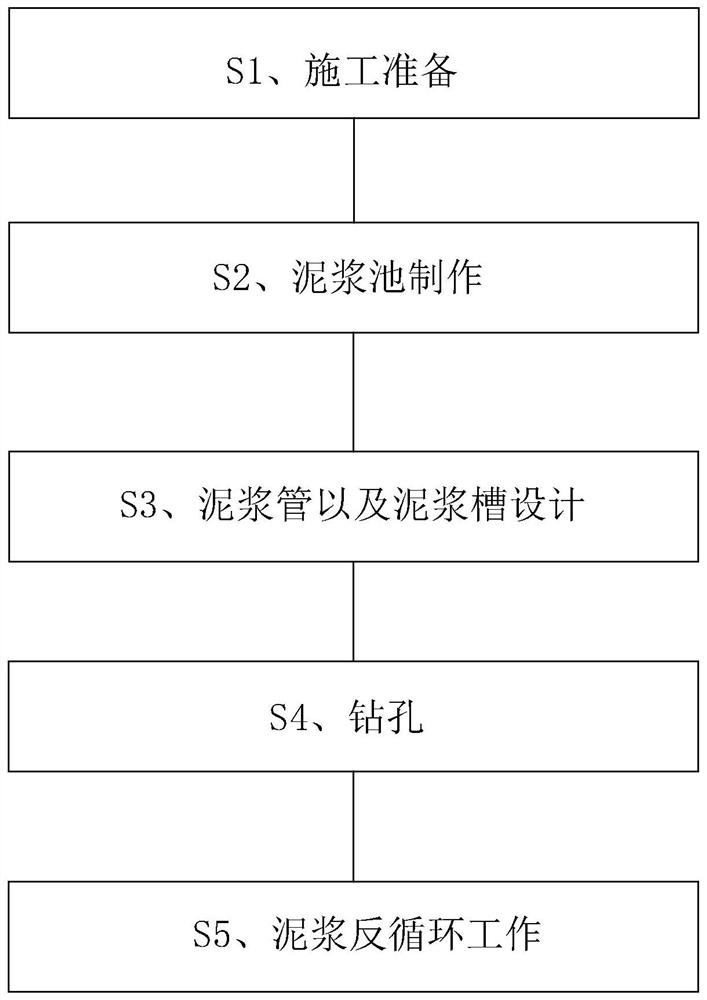
[0045] The embodiment of the present application discloses a construction method for reverse circulation and high-efficiency hole-forming of bored piles in water. refer to figure 1 and figure 2 , the reverse circulation efficient hole-forming construction method of bored piles in water includes the following steps,

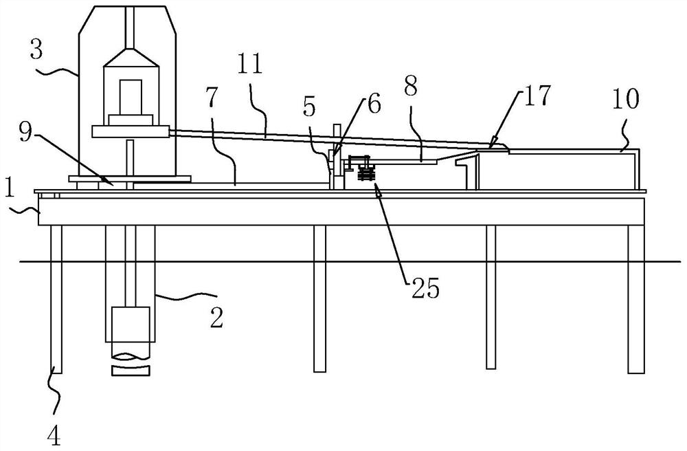
[0046] S1, construction preparation, by driving a plurality of steel pipe piles 4 in the water, the drilling platform 1 is erected above the steel pipe piles 4, and the entire drilling platform 1 is located above the horizontal plane, and then a steel casing 2 is drilled at the borehole , use a crane as a lifting device, cooperate with a vibrating hammer to insert and drill the steel casing 2, and the steel casing 2 enters the bearing layer to ensure the safety of the construction process. The drilling rig 3 is arranged on the drilling platform 1 and is located above the steel casing 2;

[0047]S2. Fabrication of the mud pool 8. Install the mud pool 8 on the dr...

Embodiment 2

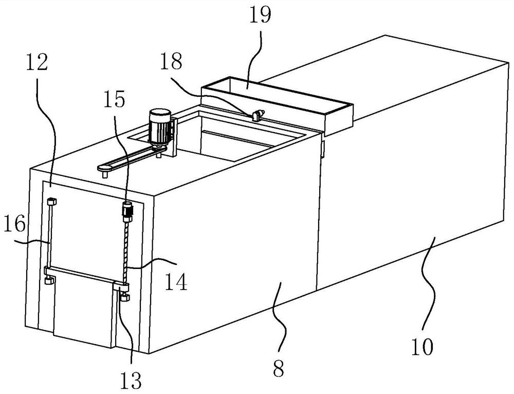
[0054] The embodiment of the present application also discloses a reverse circulation and high-efficiency hole-forming construction device for bored piles in water. refer to figure 2 and Figure 4 The reverse circulation high-efficiency pore-forming construction device for bored piles in water includes a filter device 17 arranged at the entrance of the sedimentation tank 10. Since the mud carries part of the drilling debris, in order to facilitate filtering of impurities in the mud, the filter device 17 includes The filter frame 18 fixedly connected to the sedimentation tank 10 and the filter screen 19 detachably arranged with the filter frame 18, the filter screen 19 is located at the entrance of the sedimentation tank 10, and the size of the end face of the filter screen 19 is equal to the size of the entrance of the sedimentation tank 10. When transporting When the pipe 11 transports the mud to the opening of the sedimentation tank 10, under the filtering action of the fi...


PUM


Abstract

The invention relates to an underwater cast-in-situ bored pile reverse circulation efficient hole-forming construction device and method, and relates to the field of cast-in-situ bored pile construction. The underwater cast-in-situ bored pile reverse circulation efficient hole-forming construction method comprises the following steps that construction is prepared; a mud pit is manufactured; a slurry pipe and a slurry groove are designed; holes are drilled; slurry reverse circulation work is carried out; and slurry firstly enters a settling pond before entering a slurry pit, and the slurry in the settling pond overflows into the slurry pit. According to the underwater cast-in-situ bored pile reverse circulation efficient hole-forming construction device and method, the slurry pit is arranged on a drilling platform in situ, so that the arrangement of a complex slurry long-distance pipeline is avoided, the construction difficulty is reduced, and the construction efficiency is improved; and a gate is adopted to control slurry feeding and stopping of the slurry pit, meanwhile, a slurry differential reverse circulation system is utilized to enable a water head in a steel casing to get rid of control over the slurry surface of the slurry pit, the hole collapse risk is reduced, and the hole forming efficiency is improved.

Description

technical field [0001] The present application relates to the field of cast-in-situ pile construction, in particular to a construction device and method for reverse circulation and high-efficiency hole-forming construction of bored-in-place piles in water. Background technique [0002] At present, the construction of bored piles in water often faces the problem of difficult mud pipeline layout. It is impossible to use open trenches or open grooves to supply slurry like land pile foundations. Generally, pipelines such as steel pipes or reinforced corrugated pipes are used to seal the mud pool on the shore and the steel protection in the water. The cylinder and the pile hole, using the principle of the connector, form a large flow pressure flow slurry supply system. [0003] When the above-mentioned technology is used for construction, a large number of pipelines need to be laid under the platform. Due to the poor construction environment in water, the layout is difficult, res...

Claims


Application Information

Patent Timeline
IPC IPC(8): E21B7/12E21B12/06E21B21/01E21B21/06E02D5/34
CPCE21B7/12E21B21/01E21B21/065E21B12/06E02D5/34E02D2300/0023E02D2250/0076
Inventor 钟建军吴小山尹仁贵黎辉
Owner 衡阳公路桥梁建设有限公司
Why Eureka
Try Eureka