

Titanium alloy plate laser cutting device for aerospace
A titanium alloy plate, laser cutting technology, applied in the direction of laser welding equipment, metal processing equipment, welding equipment, etc., can solve the problems of manpower consumption, unable to limit the titanium alloy plate, etc., and achieve the effect of saving manpower
- Summary
- Abstract
- Description
- Claims
- Application Information
AI Technical Summary
Problems solved by technology
Method used
Image

Examples
Embodiment 1
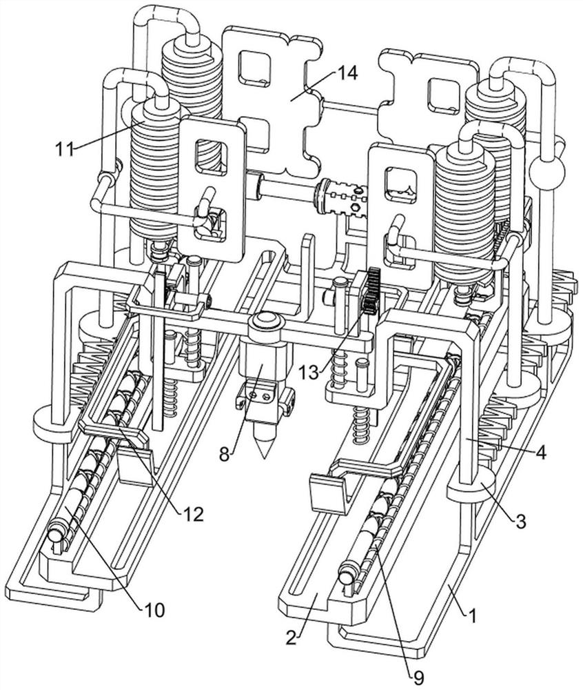
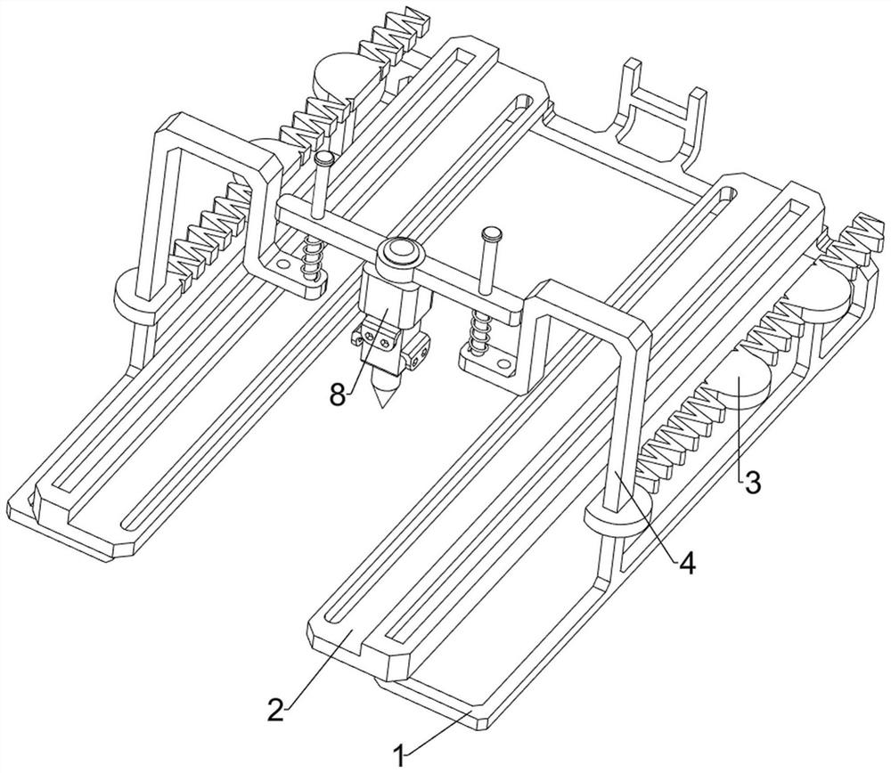
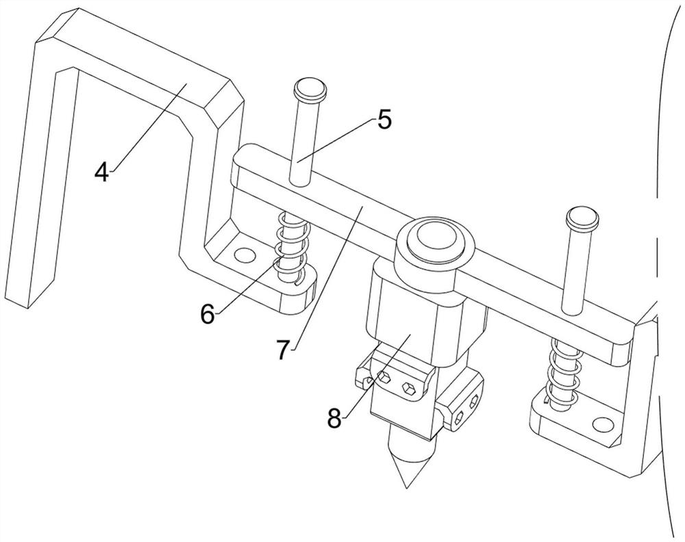
[0038] A laser cutting device for titanium alloy plates used in aerospace, such as Figure 1-7 As shown, it includes a support frame 1, a mounting plate 2, a first fixing plate 3, a first connecting plate 4, a first guide rod 5, a first spring 6, a second connecting plate 7, a laser cutter 8, and a pushing mechanism 9 and the drive mechanism 10, the left and right sides of the support frame 1 are respectively connected with a mounting plate 2 and a first fixed plate 3, the first fixed plate 3 is located outside the mounting plate 2, and the top front sides of the first fixed plate 3 on both sides are connected with The first connecting plate 4, the top of the first connecting plate 4 is connected with the first guide rod 5, and the second connecting plate 7 is slidably connected between the first guiding rods 5 on both sides, and the second connecting plate 7 is connected with two first connecting plates. A first spring 6 is connected between the plates 4, a laser cutter 8 is ...
Embodiment 2
[0043] On the basis of Example 1, such as figure 1 , Figure 8 and Figure 9 As shown, it also includes a blanking mechanism 11, and the blanking mechanism 11 includes a first fixed rod 111, a blanking plate 112, a first rotating shaft 113, a second rotating shaft 114, a one-way gear 115, a first rack 116, a flat Belt 118 and belt pulley 117, the first fixed plate 3 top rear side is connected with two first fixed rods 111, two first fixed rods 111 points are arranged front and back, and the two first fixed rods 111 on the front side are all rotationally connected There is a first rotating shaft 113, and the two first fixed rods 111 on the rear side are connected with a second rotating shaft 114 in a rotational manner, and the first rotating shaft 113 and the second rotating shaft 114 are all connected with a blanking plate 112, and the bottom of the first rotating shaft 113 Belt pulley 117 is connected with the second rotating shaft 114 bottom, flat belt 118 is wound between...
Embodiment 3
[0048] On the basis of Example 2, such as figure 1 , Figure 12 and Figure 13 As shown, a lifting mechanism 13 is also included, and the lifting mechanism 13 includes a third fixed plate 131, a third rotating shaft 132, a transmission gear 133, a second rack 134, a crank 135 and a fourth connecting plate 136, the first connecting plate 136 on the left side The upper part of the front side of the plate 4 and the upper part of the rear side of the first connecting plate 4 on the right are connected with a third fixed plate 131, the third fixed plate 131 is rotatably connected with a third rotating shaft 132, and the third rotating shaft 132 is respectively connected with a transmission gear 133 and crank 135, the crank 135 is located at the inner side of the transmission gear 133, the left and right sides of the second connecting plate 7 are connected with the fourth connecting plate 136, the fourth connecting plate 136 cooperates with the crank 135, the top of the pressing pl...
PUM
 Abstract
Description
Claims
Application Information