Supercharge Your Innovation With Domain-Expert AI Agents!

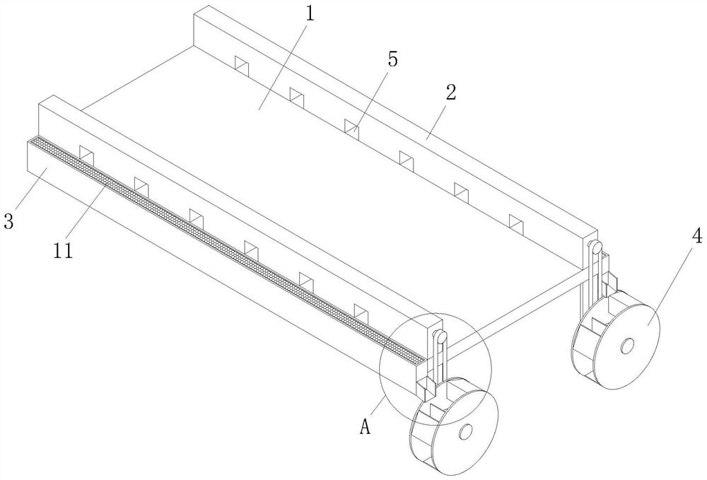
A bridge engineering drainage structure

A technology of drainage structure and bridge engineering, applied in the direction of bridges, bridge parts, bridge construction, etc., can solve problems such as blockage of drains, water accumulation in bridges, and unsmooth drainage, and achieve the effect of avoiding blockage

Active Publication Date: 2021-12-07
岳伟
View PDF6 Cites 2 Cited by
  • Summary
  • Abstract
  • Description
  • Claims
  • Application Information

AI Technical Summary

Problems solved by technology

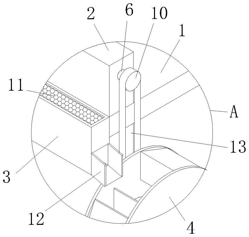
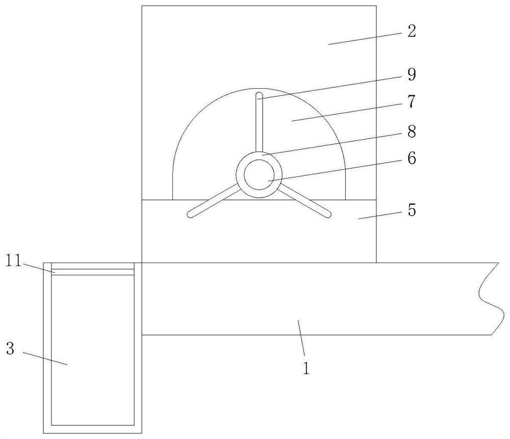
[0004] In order to solve the problem that the drainage outlet of the bridge retaining wall is often blocked when the drainage outlet is drained, which makes the drainage unsmooth and causes water accumulation in the bridge, the purpose of the present invention is to provide a drainage structure for bridge engineering

Method used


Image

  • A bridge engineering drainage structure
  • A bridge engineering drainage structure
  • A bridge engineering drainage structure

Examples


Embodiment Construction

[0022] The implementation of the present invention will be illustrated by specific specific examples below, and those skilled in the art can easily understand other advantages and effects of the present invention from the contents disclosed in this specification.

[0023] see Figure 1 to Figure 4 . It should be noted that the structures, proportions, sizes, etc. shown in the drawings attached to this specification are only used to match the content disclosed in the specification, for those who are familiar with this technology to understand and read, and are not used to limit the implementation of the present invention. Limiting conditions, so there is no technical substantive meaning, any modification of structure, change of proportional relationship or adjustment of size, without affecting the effect and purpose of the present invention, should still fall within the scope of the present invention. The disclosed technical content must be within the scope covered. At the sa...


PUM


Abstract

The invention discloses a bridge engineering drainage structure, which comprises a bridge slab, the base surface of the bridge slab near the edge is symmetrically fixedly connected with two retaining walls, and the side walls are symmetrically fixedly connected with two water guide grooves, and the bottom A driving mechanism is installed; the side wall of the retaining wall is provided with several water outlets, and the side wall is rotated and connected with a rotating rod. The top of the water outlet is provided with an arc groove, and the rotating rod passes through the shaped groove, and the outer wall located inside the arc-shaped groove is fixedly sleeved with a collar, and the outer wall of the collar is fixedly connected with three mud-pushing plates in an annular array, and one end of the rotating rod located outside the retaining wall is pivotally connected with a first Belt pulley, the invention relates to the technical field of bridge engineering. The invention solves the problem that the drain outlet of the bridge retaining wall often encounters the situation that the drain outlet is blocked when draining water, so that the drainage is not smooth, so that the bridge has water accumulation.

Description

technical field [0001] The invention relates to the technical field of bridge engineering, in particular to a bridge engineering drainage structure. Background technique [0002] With the increase of the frequency of rainstorms in various places, the bridge deck drainage problem of urban viaducts has been highly concerned by people, and it is particularly important to improve the existing drainage system of urban viaducts and develop new drainage systems. Due to the long distance of the urban viaduct and its location in a relatively closed environment, the exchange of water flow with the outside world can only enter the drainage pipe through the rainwater outlet set on the bridge deck and finally enter the municipal pipe under the bridge. [0003] In the prior art, when the drainage outlet of the bridge retaining wall is drained, the drainage outlet is often blocked, which makes the drainage not smooth, thus causing the bridge to accumulate water. Contents of the invention...

Claims


Application Information

Patent Timeline
Patent Type & Authority Patents(China)
IPC IPC(8): E01D19/08B01D35/027
CPCB01D35/027E01D19/086
Inventor 陈婉珍洪伟杰
Owner 岳伟
Features
  • R&D
  • Intellectual Property
  • Life Sciences
  • Materials
  • Tech Scout
  • Unparalleled Data Quality
  • Higher Quality Content
  • 60% Fewer Hallucinations
Learn More