
An oil pipeline connection mechanism for convenient sampling in oil exploitation

A connection mechanism, oil extraction technology, applied in flange connection, pipeline system, pipe/pipe joint/pipe fitting, etc., can solve the problems of inconvenient sampling operation, increase construction difficulty, inconvenient pipeline maintenance, etc., and achieve convenient linkage coordination Operation, convenient laying and installation, and the effect of improving laying efficiency

Active Publication Date: 2022-06-21
山东卓锐石化科技有限公司
View PDF11 Cites 0 Cited by
  • Summary
  • Abstract
  • Description
  • Claims
  • Application Information

AI Technical Summary

Problems solved by technology

[0005] The object of the present invention is to provide a kind of petroleum pipeline connecting mechanism that is applied to convenient sampling in petroleum exploitation, in order to solve the existing petroleum on the market proposed by the above-mentioned background technology when transporting through pipelines, in the process of sampling, due to The transportation pipelines are sealed connections. When the pipelines are installed, it is necessary to open a reserved opening for sampling on the outer wall of the pipeline, which increases the difficulty of construction. When the pipeline is damaged, the entire pipeline needs to be replaced and the sampling reservation needs to be re-opened. It is inconvenient for subsequent maintenance of the pipeline, and when oil sampling is required, it is inconvenient to quickly connect the sampling tube with the reserved opening of the pipeline, and it is inconvenient for the sampling operation

Method used


Image

  • An oil pipeline connection mechanism for convenient sampling in oil exploitation
  • An oil pipeline connection mechanism for convenient sampling in oil exploitation
  • An oil pipeline connection mechanism for convenient sampling in oil exploitation

Examples


Embodiment Construction

[0029] Based on the embodiments of the present invention, all other embodiments obtained by those of ordinary skill in the art without creative efforts shall fall within the protection scope of the present invention.

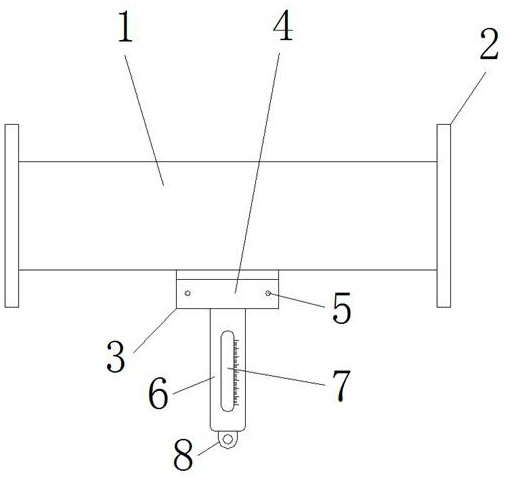
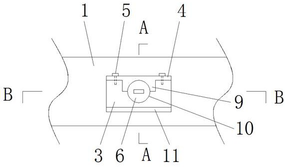
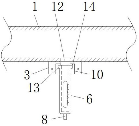
[0030] see Figure 1-10 , The present invention provides a technical solution: a petroleum pipeline connection mechanism for convenient sampling in oil exploitation, comprising a connection mechanism body 1, a flange 2, a connection seat 3, a fixing plate 4, bolts 5, sampling pipes 6, Observation window 7, hanging ring 8, pressing block 9, blocking groove 10, limit plate 11, sampling port 12, sliding block 13, guide groove 14, blocking block 15, sliding groove 16, spring 17, blocking head 18 , limit elastic piece 19, installation groove 20 and limit groove 21, both ends of the connection mechanism body 1 are welded with flanges 2, and the middle of the lower end of the connection mechanism body 1 is welded with a connection seat 3, and the front side of the conn...


PUM


Abstract

The invention discloses a petroleum pipeline connection mechanism for convenient sampling in petroleum exploitation, which comprises a connection mechanism body, a flange, a connection seat, bolts, a sampling tube, an observation window, a hanging ring, a spring and a plugging head. Both ends of the connecting mechanism body are welded with flanges, and the middle part of the lower end of the connecting mechanism body is welded with a connecting seat, and the two sides of the sampling tube away from the end of the hanging ring are welded with sliding blocks, and the sampling tube is connected with the connecting block through the sliding block. The guide groove on the inner side of the seat is slidably connected, and the end of the sampling tube close to the sliding block is an open structure, and the inside of the sampling tube communicates with the sampling port on the connecting mechanism body through the opening. The oil pipeline connection mechanism used for convenient sampling in oil exploitation, through the improvement of the existing oil pipeline connection, can conveniently carry out fixed-distance sampling detection on oil transportation pipelines, and does not need to carry out pipeline inspection when laying pipelines. Additional openings are reserved to improve the efficiency of pipeline laying.

Description

technical field [0001] The invention relates to the technical field of oil extraction pipelines, in particular to an oil pipeline connection mechanism used for convenient sampling in oil extraction. Background technique [0002] After the oil is extracted, it needs to be transported through the pipeline. In the process of oil extraction and transportation, due to the need to test the quality of the oil, it is necessary to regularly sample the oil in the pipeline to facilitate the transportation of oil in the oil pipeline. Quality control, so that oil extraction and refining can operate normally, but when the existing oil is transported through pipelines, there are the following problems in the process of sampling: [0003] 1. When oil normally passes through the transportation pipeline, due to the sealed connection between the transportation pipelines, when the pipeline is installed, it is necessary to open a reserved port for sampling on the outer wall of the pipeline, whic...

Claims


Application Information

Patent Timeline
Patent Type & Authority Patents(China)
IPC IPC(8): F16L41/12F16L41/08F16L55/11F16L23/00F17D5/00
CPCF16L41/12F16L41/08F16L55/1108F16L23/00F17D5/00
Inventor 吕友飞
Owner 山东卓锐石化科技有限公司
Learn More