A cutting edge and corner device for tape measure processing

A technology of measuring tape and corners, applied in the direction of shearing devices, accessories of shearing machines, metal processing equipment, etc., can solve the problems of tediousness, safety accidents, etc., and achieve the effect of ensuring safety and simple operation

Inactive Publication Date: 2021-07-30
苏运研
View PDF7 Cites 0 Cited by
  • Summary
  • Abstract
  • Description
  • Claims
  • Application Information

AI Technical Summary

Problems solved by technology

[0005] In order to overcome the disadvantages that the process of manual edge trimming is cumbersome, and operation errors during edge trimming are likely to cause safety accidents, the purpose of the present invention is to provide an edge trimming device for tape measure processing that is easy to operate and can ensure the safety of workers

Method used


Image

  • A cutting edge and corner device for tape measure processing
  • A cutting edge and corner device for tape measure processing
  • A cutting edge and corner device for tape measure processing

Examples


Embodiment 1

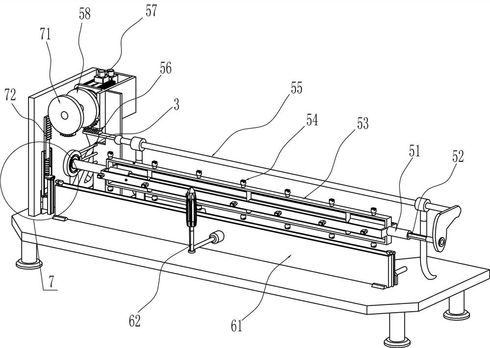
[0026] A trimming device for tape measure processing, such as Figure 1-6 As shown, it includes installation platform 1, installation frame 2, installation plate 3 and guide sleeve 4, installation frame 2 is connected to the top of installation platform 1, installation frame 2 is connected to installation platform 1 through bolts, installation frame 2 and installation platform 1 The top is connected with a mounting plate 3, the top of the mounting table 1 is connected with a guide sleeve 4 on both sides, and also includes a feeding assembly 5, a discharging assembly 6 and a cutting assembly 7, and a feeding assembly is provided between the mounting plate 3 and the mounting table 1 5. There is a discharge assembly 6 on the installation platform 1. The discharge assembly 6 is used to place the tape that needs trimming. A cutting assembly 7 is provided between the installation frame 2 and the installation platform 1.

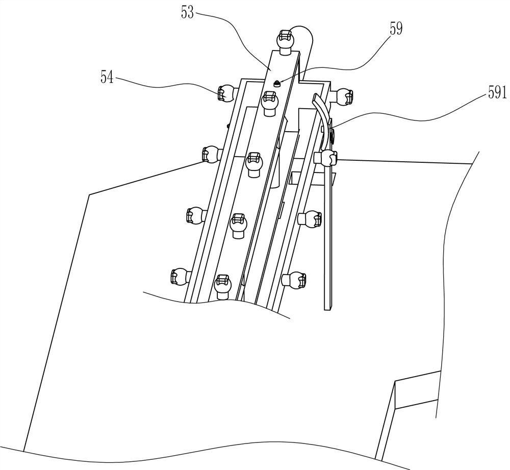
[0027] The feeding assembly 5 includes an inner diamond-shape...

Embodiment 2

[0032] On the basis of Example 1, such as Figure 7 As shown, a rotating assembly 8 is also included. The rotating assembly 8 includes a driving gear 81, a rotating shaft 82 and a bevel gear 83. The upper part of the inner wall of the installation frame 2 is rotatably connected with a driving gear 81 that will mesh with the first sector gear 58. The installation frame 2 The lower part of the inner wall is rotatably connected with a rotating shaft 82, and the rotating shaft 82 is connected with the inner rhombic sleeve 51 with a bevel gear 83. The bevel gear 83 is used to drive the inner rhombic sleeve 51 to rotate. The drive gear 81 is in transmission connection.

[0033] When the first sector gear 58 rotates to mesh with the drive gear 81, the first sector gear 58 continues to rotate to drive the drive gear 81 to rotate, the drive gear 81 rotates the rotating shaft 82, and the rotating shaft 82 rotates through the internal rhombic sleeve 51 driven by the bevel gear 83 Rotate...

Embodiment 3

[0035] On the basis of Example 2, such as Figure 8 As shown, it also includes an arc inclined block 9, a disc 10 and a contact rod 11, and the right side of the right mounting plate 3 is connected with an arc inclined block 9, and the arc inclined block 9 is connected to the mounting plate 3 by bolts. Connected, rhombus bar 52 is connected with disc 10, and disc 10 is connected with contact rod 11, and contact rod 11 is connected with disc 10 by the mode of welding connection, and contact rod 11 cooperates with arc oblique block 9.

[0036] When the diamond-shaped rod 52 moves toward the installation frame 2, it drives the disc 10 to move toward the installation plate 3. When the rhombus rod 52 moves to the extreme, the contact rod 11 contacts the arc-shaped inclined block 9. When the rotating assembly 8 drives the diamond-shaped rod 52 When rotating, the rhombus rod 52 drives the disc 10 to rotate, and the disc 10 rotates to drive the contact rod 11 to rotate, and the contac...


PUM


Abstract

The invention relates to an edge trimming device, in particular to an edge trimming device for tape measure processing. The purpose of the present invention is how to design an edge trimming device for tape measure processing which is easy to operate and can ensure the safety of workers. A corner trimming device for tape measure processing, including a mounting table, a mounting frame is fixedly connected to the top of the mounting table, and guide sleeves are fixedly connected to both sides of the top of the mounting table; two mounting plates are provided, one of which is installed on the The side wall of the frame, the other is installed on the top of the installation table; the feeding component is installed between the installation plate and the installation table, and is used to transport the tape that needs to be trimmed. In the present invention, the tape measure that needs to be trimmed is placed through the feeding component, and after the placement is completed, the tape that needs to be trimmed can be trimmed through the cooperation of the feeding component and the cutting component, so that the effect of trimming can be achieved.

Description

technical field [0001] The invention relates to an edge trimming device, in particular to an edge trimming device for tape measure processing. Background technique [0002] The tape measure is a commonly used measuring tool in daily life. It is mostly used in construction or decoration. What you often see is a steel tape measure, which is also one of the necessary tools for the family. In the process of making the tape measure, it is usually placed on the tape measure. There are some extra corners at one end, and these corners need to be cut off manually by workers before they can be used. [0003] At present, the way to cut off the extra corners of the tape measure is generally to have workers place one end of the tape measure on the trimming device, and then move down the edge-cutting part to trim the tape measure, and the trimming is completed Afterwards, the trimming parts are lifted, and the trimming process is relatively cumbersome for the workers. In addition, the tr...

Claims


Application Information

Patent Timeline
Patent Type & Authority Patents(China)
IPC IPC(8): B23D33/02B23D33/00B23D31/00
CPCB23D31/00B23D33/00B23D33/02
Inventor 苏运研班虎
Owner 苏运研
Why Eureka
Try Eureka