Method and system for monitoring hidden faults of power supply equipment

A technology for hidden faults and power supply equipment, which is applied in fault location, information technology support system, fault detection according to conductor type, etc. It can solve the problems of unsuitable traveling wave analysis method, difficult real-time application of ultrasonic monitoring method, and unpredictable fault point, etc.

Active Publication Date: 2021-09-24
BEIJING SIFANG JIBAO ENG TECH +2
View PDF5 Cites 0 Cited by
  • Summary
  • Abstract
  • Description
  • Claims
  • Application Information

AI Technical Summary

Problems solved by technology

[0004] Existing fault monitoring methods for power supply equipment have various shortcomings that limit their wide application
For example, the ultrasonic monitoring method relies on external signals and is difficult to apply in real time. The traveling wave analysis method is not suitable for short lines or equipment. The electromagnetic coupling method for testing partial discharge needs to install a built-in partial discharge sensor, which is difficult to adopt in existing equipment. Wavelet analysis method and neural network method It is greatly affected by the type of fault point and interference type
Therefore, there is no perfect monitoring method for hidden faults of power supply equipment for a wide range of fault types.
[0005] In addition, it should be pointed out that temperature rise is also a common feature of power supply equipment failure, but the measurement sensitivity of temperature rise is much lower than the measurement of transmission power loss, which is not conducive to early detection of faults
In addition, the abnormal temperature can be detected in time only when the temperature sensor is installed near the fault point. However, the fault point is often difficult to predict, or there are too many sensors to install a large number of sensors.

Method used


Image

  • Method and system for monitoring hidden faults of power supply equipment
  • Method and system for monitoring hidden faults of power supply equipment
  • Method and system for monitoring hidden faults of power supply equipment

Examples


Embodiment approach

[0072] attached Figure 4 It is an example of a one-line diagram of a part of a 6kV / 0.4kV substation. In the figure, 401, 402, 403, and 404 are the numbers of the corresponding branch switch cabinets. The figure also exemplarily draws a remote power supply through cables. motor load. The operator hopes to timely discover the faults such as poor contact, discharge, insulation breakdown and other faults in the power supply equipment such as the switch cabinets, switches, and the cable joints of the power supply cables to the load. Timely detection and early warning of internal or external faults of power supply equipment such as transformers and capacitors. Embodiments using the methods and systems disclosed in this patent are as follows:

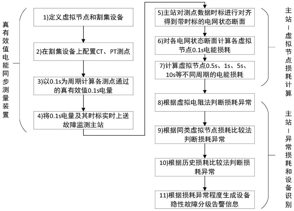
[0073] attached figure 1 Shown is a schematic flowchart of a method for monitoring a hidden fault of a power supply device based on the true RMS measurement of power loss disclosed in the present invention, and the method for monitoring a ...


PUM


Abstract

The present disclosure relates to a method and a system for monitoring hidden faults of grid power supply equipment. The method defines a virtual node including several power supply devices, calculates the true RMS electric energy flowing into the virtual node and the true RMS electric energy flowing out of the virtual node within 0.1s in real time with a period of 0.1s, and marks it with precise time scale. Then, the electrical energy losses occurring in the virtual nodes are continuously calculated over a time window of multiple cycle scales. Finally, through the virtual resistance method, the loss comparison method of similar virtual nodes, and the historical loss comparison method, it is judged whether there is a hidden fault in the internal equipment of the virtual node. The system based on this method includes a true effective value electric energy synchronous measuring device and a hidden fault monitoring station domain master station of power supply equipment, which is suitable for monitoring non-control circuit faults of power supply equipment.

Description

technical field [0001] The invention belongs to the technical field of power grid fault diagnosis, and in particular relates to a method and system for latent fault monitoring of power supply equipment. Background technique [0002] The power grid relies on a large number of lines, switches, transformers, capacitors, frequency converters and other power supply equipment to complete the transmission of electrical energy from power generation equipment to electrical equipment. These power supply devices themselves or their interconnected joints, contacts and insulation may often have poor contact, discharge or non-metallic short circuit problems, resulting in heat generation, which may eventually lead to fire or explosion, which seriously affects the safety of power transmission and power supply. This is especially common in low voltage supply systems of 400V or 6kV. For example, poor contact occurs at the drawer inlet of a 400V switch cabinet in a chemical enterprise, which ...

Claims


Application Information

Patent Timeline
Patent Type & Authority Patents(China)
IPC IPC(8): H02J13/00G01R31/08
CPCG01R31/086G01R31/088H02J13/00006H02J13/00017H02J13/00022Y02E60/00Y04S10/40Y04S40/12Y04S40/124Y04S40/126
Inventor 段刚娄霄楠张琦谭勇王志华孙玉恒郭芳刘世海李莉
Owner BEIJING SIFANG JIBAO ENG TECH
Why Eureka
Try Eureka