Multi-backup otdr optical amplifying device with shared light source and control method

An optical amplification and light source technology, applied in electrical components, electromagnetic wave transmission systems, transmission systems, etc., can solve the problems of high cost, high complexity of optical network maintenance, and high equipment prices, and achieve the effect of saving equipment costs.

Active Publication Date: 2018-11-20
WUXI TACLINK OPTOELECTRONICS TECH CO LTD
View PDF6 Cites 0 Cited by
  • Summary
  • Abstract
  • Description
  • Claims
  • Application Information

AI Technical Summary

Problems solved by technology

The optical time domain reflectometer (OTDR) is tested by directly connecting the optical fiber or inserting optical pulses of specific wavelengths into the optical fiber. The test networking scheme is complicated and the price of OTDR equipment is high.
The above factors lead to high complexity and high cost of optical network maintenance with monitoring optical fiber function
Moreover, OTDR equipment is expensive equipment. Once the built-in laser light source is damaged, the OTDR equipment needs to be replaced, which further increases the maintenance cost of the optical network.

Method used


Image

  • Multi-backup otdr optical amplifying device with shared light source and control method
  • Multi-backup otdr optical amplifying device with shared light source and control method
  • Multi-backup otdr optical amplifying device with shared light source and control method

Examples


Embodiment Construction

[0040] The present invention will be further described below in conjunction with specific drawings and embodiments.

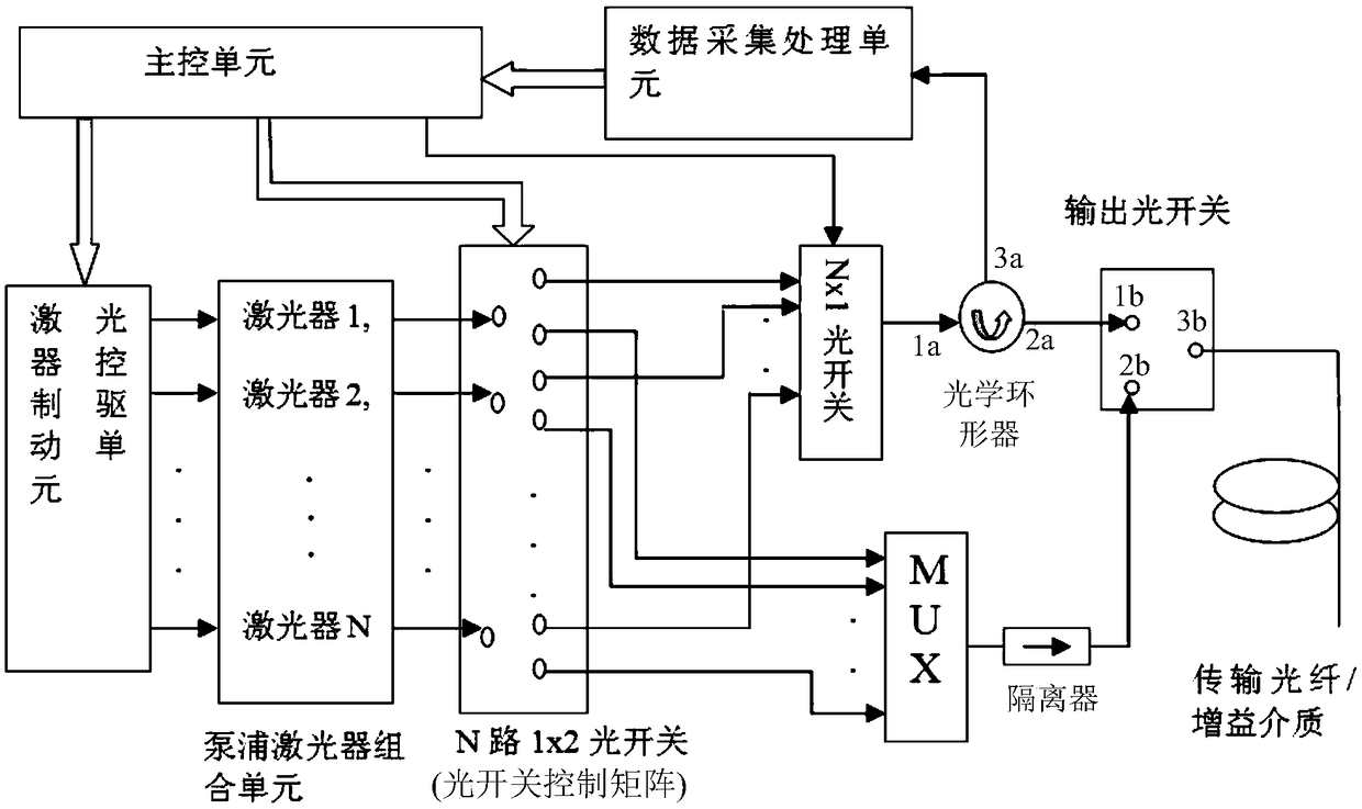
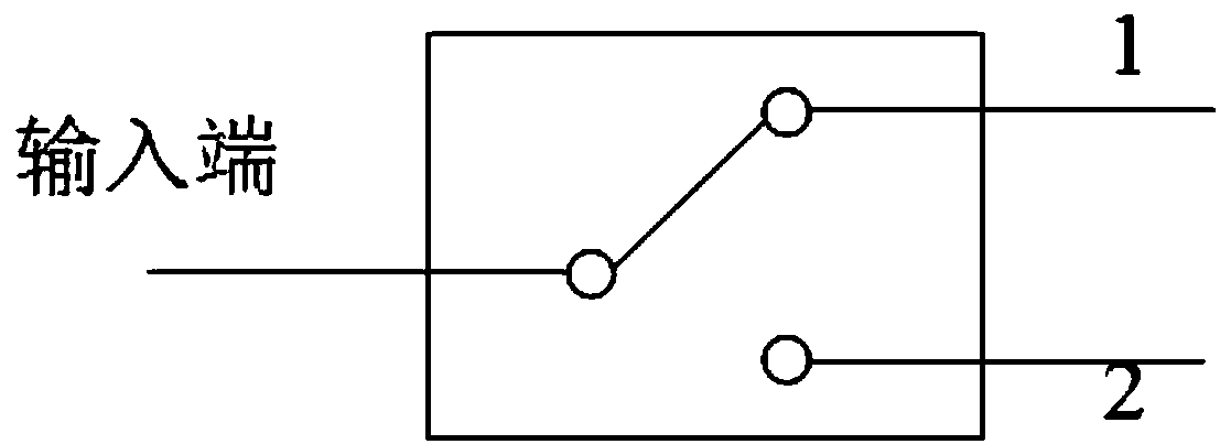
[0041] The present invention proposes a multi-backup OTDR optical amplifying device of a shared light source, such as figure 1 As shown, it includes: main control unit, data acquisition and processing unit, laser control drive unit, pump laser combination unit composed of N pump lasers, optical switch control matrix, Nx1 optical switch, optical circulator, output optical switch, pump A beam combiner MUX; N 1x2 optical switches are set in the optical switch control matrix; N≥2;

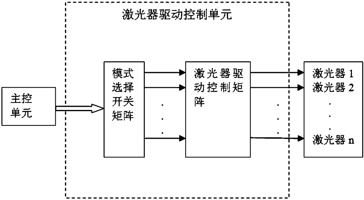
[0042] Such as figure 2 As shown, the laser control drive unit includes a mode selection switch matrix and a laser control drive matrix; there are N drive units in the laser control drive matrix; the main control unit is connected to and controls the mode selection switch matrix; the N output of the mode selection switch matrix The terminals are respectively connected to control the ...


PUM


Abstract

The invention provides a multi-backup OTDR optical amplification device with a shared light source. The device comprises a pump laser combination unit composed of a main control unit, a data collecting and processing unit, a laser control driving unit and N pump lasers, an optical switch control matrix, N*1 optical switches, an optical circulator, an output optical switch and a pump combiner MUX; N 1*2 optical switches are arranged in the optical switch control matrix; N is not smaller than 2; the laser control driving unit comprises a mode selection switch matrix and a laser control driving matrix; N driving units are arranged in the laser control driving matrix; the main control unit is connected with and controls the mode selection switch matrix; the driving units in the laser control driving matrix are separately connected with the corresponding pump lasers in the pump laser combination unit; and the multi-backup OTDR optical amplification device provided by the invention shares the pump lasers to achieve a built-in OTDR function of the optical amplification device, and the backup light source improves the reliability of OTDR.

Description

technical field [0001] The invention relates to the field of optical fiber communication, in particular to an OTDR optical amplifying device with multiple backups of a shared light source used in the field of optical fiber communication. Background technique [0002] The English full name of Optical Time Domain Reflectometer (OTDR) is Optical Time Domain Reflectometer. OTDR is a precision optoelectronic integrated instrument made by using Rayleigh scattering and backscattering produced by Fresnel reflection when optical signals are transmitted in optical fibers. It is widely used in the maintenance and construction of optical cable lines. It can measure the length of optical fiber, transmission attenuation of optical fiber, joint attenuation and fault location. [0003] At present, long-distance transmission systems are generally inseparable from erbium-doped optical fiber amplifiers, Raman optical amplifiers, or hybrid optical fiber amplifiers composed of the two. Before ...

Claims


Application Information

Patent Timeline
Patent Type & Authority Patents(China)
IPC IPC(8): H04B10/071H04B10/077
CPCH04B10/071H04B10/077
Inventor 迟荣华丰云宾
Owner WUXI TACLINK OPTOELECTRONICS TECH CO LTD
Why Eureka
Try Eureka