A distributed optical fiber temperature sensor temperature accuracy testing system and method

A distributed optical fiber and temperature sensor technology, which is applied in thermometer testing/calibration, thermometers, instruments, etc., can solve the problems of few measurement points, manual attention to thermometers, out-of-synchronization of time optical fiber sensor measurement, etc., to achieve verification accuracy and ensure accuracy sexual effect

Active Publication Date: 2021-11-26
GUANGDONG POWER GRID CO LTD +1
View PDF5 Cites 0 Cited by
  • Summary
  • Abstract
  • Description
  • Claims
  • Application Information

AI Technical Summary

Problems solved by technology

However, there is no uniform test standard for the existing Brillouin-type distributed optical fiber sensor temperature accuracy test method. There are many deficiencies in the comparison of temperature: (1) only one point or multiple points are selected for comparison with a point thermometer, and the number of comparison measurement points is very small, and the measurement of the thermometer and the measurement of the optical fiber sensor are not synchronized in time; (2) It is necessary to manually pay attention to the changes of the thermometer, and it is difficult to carry out real-time fine measurement of the dynamic changes of temperature in a long distance

Method used


Image

  • A distributed optical fiber temperature sensor temperature accuracy testing system and method
  • A distributed optical fiber temperature sensor temperature accuracy testing system and method
  • A distributed optical fiber temperature sensor temperature accuracy testing system and method

Examples


Embodiment 1

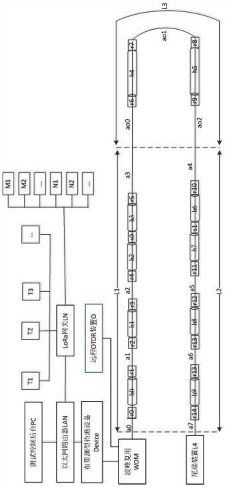
[0039] This embodiment is an embodiment of a distributed optical fiber temperature sensor temperature accuracy test system, which includes a sequentially connected test control background PC, Ethernet router LAN, Brillouin type device to be tested, wave peak multiplexing WDM, optical cable L and tail Terminal device L4:

[0040] The optical cable L includes two sets of cable cores l1 and l2. The optical cable includes the starting end of the L1 optical cable located indoors, the outdoor end of the L2 optical cable located outdoors, and the end of the L3 optical cable located indoors. The initial end of the L1 optical cable is connected to the peak multiplexing WDM. The outdoor end of the optical cable is connected to the end device L4, and a heating cable group h is arranged inside the optical cable;

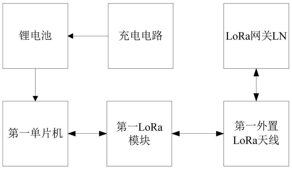
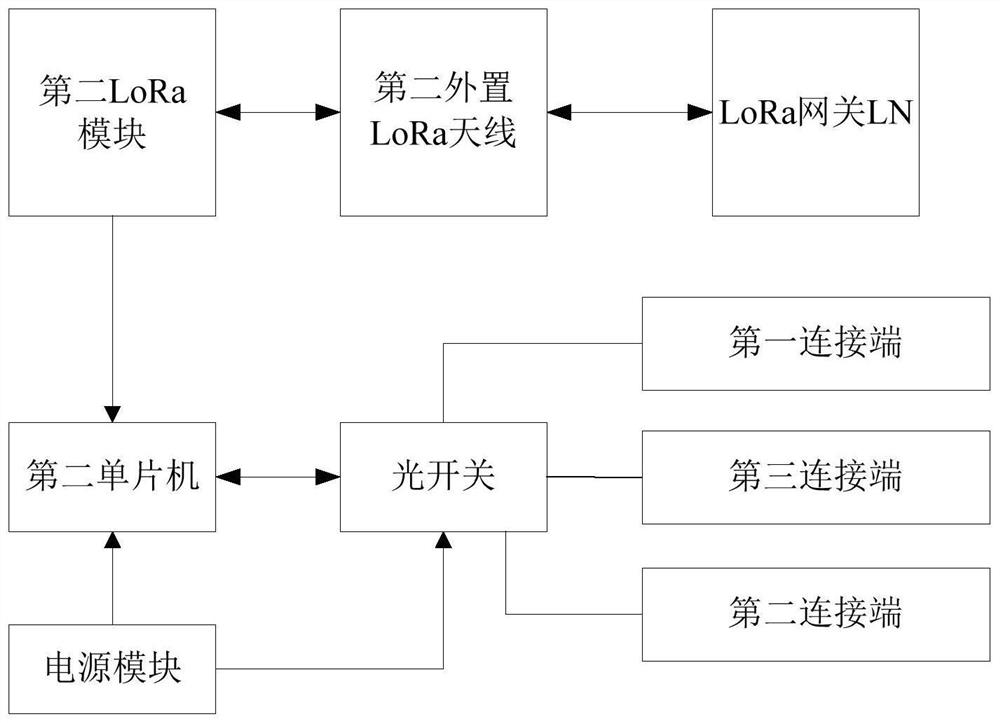
[0041] The Ethernet router LAN is connected with a LoRa gateway LN for Ethernet and LoRa protocol conversion and control, and the LoRa gateway LN is connected with a heating cab...

Embodiment 2

[0050] This embodiment is an embodiment of a temperature accuracy test method for a distributed optical fiber temperature sensor, including a line loss test method, a static temperature accuracy test method, a dynamic temperature accuracy test method, and a temperature mutation event measurement and positioning performance test method, wherein:

[0051] Line loss test method: According to the Brillouin type DUT, control the end device L4 to connect the cable core l1, cable core l2, and control the remote OTDR device O for testing, and compare the measured line loss with the initial value: if If there is an abnormality, stop all tests and send an alarm; if it is normal, end the line loss test and enter the static temperature accuracy test and dynamic temperature accuracy test;

[0052] Static temperature accuracy test method: set the average temperature collection time, data upload interval and total test length; take the time value of the Brillouin type device under test as the...


PUM


Abstract

The present invention relates to the technical field of power grid monitoring, more specifically, to a distributed optical fiber temperature sensor temperature accuracy testing system and method, including sequentially connected test control background PC, Ethernet router LAN, and Brillouin type equipment to be tested Device, peak multiplexing WDM, optical cable L and end device L4: Ethernet router LAN is connected to LoRa gateway LN, LoRa gateway LN is connected to heating cable control device group T and temperature test node group: heating cable control device group T is for heating The heating control of the cable group h, the temperature test node group includes the first temperature test node group M uniformly distributed on the optical fiber and the second temperature set at the boundary between the optical cable L and the heating cable group h or two adjacent heating cable groups The test node group N is connected with a remote OTDR device O with LoRa function in the peak multiplexing WDM. The invention synchronizes the optical fiber sensor measurement with the measurement data of the temperature test node, and can realize real-time fine measurement of long-distance temperature dynamic changes.

Description

technical field [0001] The invention relates to the technical field of power grid monitoring, and more specifically, to a temperature accuracy testing system and method of a distributed optical fiber temperature sensor. Background technique [0002] Optical fiber sensing technology has the advantages of anti-electromagnetic interference, essential anti-riot, anti-lightning strike, no power supply on site, small size, light weight, high sensitivity, low loss, long-distance and remote monitoring, and long-term online monitoring. It is currently the most cutting-edge measurement One of the techniques. Among them, the distributed optical fiber sensor based on the Brillouin scattering effect is optimal in monitoring distance, response time and other indicators, and can monitor the continuous distribution of temperature and stress information in time and space along the path of the optical fiber. Application prospects, in the temperature and strain monitoring of long-distance pow...

Claims


Application Information

Patent Timeline
Patent Type & Authority Patents(China)
IPC IPC(8): G01K15/00
CPCG01K15/007
Inventor 赵尊慧孙廷玺王旭峰王升张真毅黄毓华崔江静鲁晓一方义治吴伟文
Owner GUANGDONG POWER GRID CO LTD
Why Eureka
Try Eureka