Tension-adjustable slip shaft

A slip shaft and tension technology, applied in the field of slip shaft, can solve problems affecting production efficiency and troublesome replacement process

Pending Publication Date: 2020-09-25
上海承秉机械有限公司
View PDF1 Cites 0 Cited by
  • Summary
  • Abstract
  • Description
  • Claims
  • Application Information

AI Technical Summary

Problems solved by technology

However, in actual production, when products of different types or specifications are produced, the tension required for winding is also different.

Method used


Image

  • Tension-adjustable slip shaft
  • Tension-adjustable slip shaft
  • Tension-adjustable slip shaft

Examples


Embodiment Construction

[0032] The present invention will be described in further detail below in conjunction with the accompanying drawings.

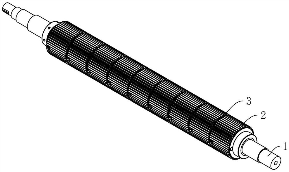
[0033] refer to figure 1 and figure 2 , is a tension-adjustable slip shaft disclosed by the present invention, which includes a cylindrical air shaft main body 1 and a plurality of slip rings 2 installed on the air shaft main body 1, and spacer rings are sleeved on the air shaft main body 1 3. The spacer ring 3 is located between the adjacent slip rings 2 , and the spacer ring 3 isolates the adjacent slip rings 2 .

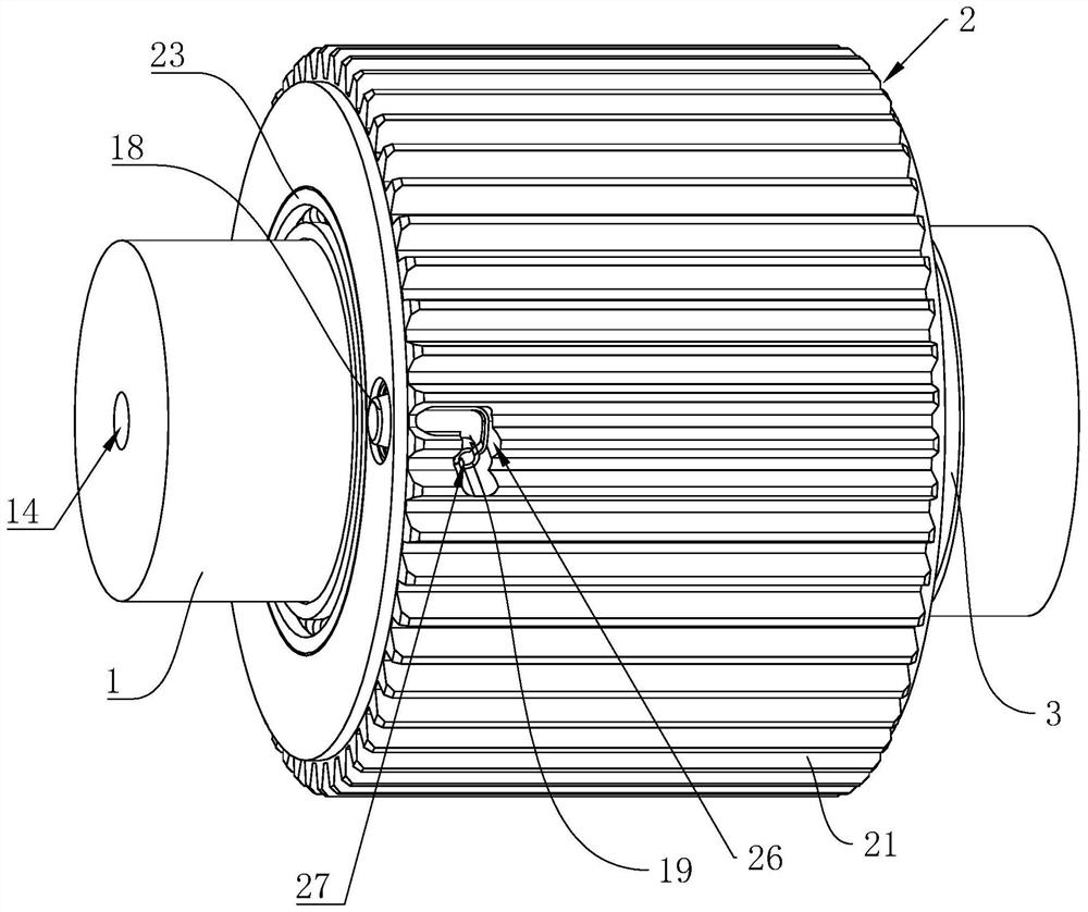
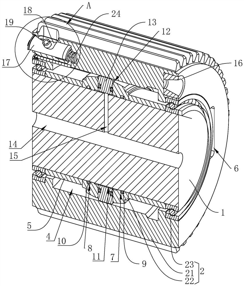
[0034] refer to figure 2 and image 3, the slip ring 2 includes a gear ring 21, a tension ring body 22 and an end bearing 23, all of which are in the shape of a ring, wherein the tension ring body 22 and the end bearing 23 are sleeved on the air shaft main body 1, and the gear ring 21 The end face bearing 23 is sleeved on the end face bearing 23 to support the gear ring 21 .

[0035] The outer wall of the tension ring body 22 is arranged i...


PUM


Abstract

The invention relates to a tension-adjustable slip shaft, and relates to the technical field of slip shafts. The slip shaft comprises an air shaft main body and a plurality of slip rings mounted on the air shaft main body, each slip ring comprises a gear ring, a tension ring body and an end face bearing, both the tension ring bodies and the end face bearings sleeve the air shaft main body, the gear rings sleeve the end face bearings, air inlet ring grooves are formed in the inner walls of the tension ring bodies, piston holes are formed in the groove bottoms of the air inlet ring grooves, piston bodies are installed in the piston holes, an intake header pipe is arranged on the air shaft main body, an intake branch pipe is arranged on the side wall of the intake header pipe, a plug-in cylinder body is installed at one end of each gear ring, a fixed sleeve is installed at the other end of each gear ring, plug-in posts are slidably installed in the fixed sleeves, deflector rods are fixedly arranged on the side walls of the plug-in posts, a sliding groove and a limit part are arranged on the side wall of each fixed sleeve, springs are installed in the fixed sleeves, adjustment groovesare formed in the side walls of the gear rings, and the deflector rods are located in the adjustment grooves. The slip shaft has the characteristics of adjustable tension, wide application range and non-replacement.

Description

technical field [0001] The invention relates to the technical field of slip shafts, in particular to a slip shaft with adjustable tension. Background technique [0002] The slip shaft, also known as the friction shaft, has a special structure and consists of multiple slip rings. It is mainly used in the rewinding shaft of the slitting machine, and it is also used in the unwinding shaft in special occasions. The purpose is to use the principle of slipping of each slip ring on the slip shaft to make multiple rolls on the shaft maintain constant tension for rewinding and unwinding. . [0003] In the Chinese invention patent with the application number CN201721824161.8, a slip shaft with a single air path structure is disclosed, including a retaining ring, a slanting block and an expansion sleeve. One end of the retaining ring is embedded with one end of the slanting block, and the retaining ring A bearing is fixedly installed inside one end, and an expansion sleeve is install...

Claims


Application Information

Patent Timeline
IPC IPC(8): B65H75/24B65H75/18
CPCB65H75/18B65H75/243
Inventor 杨代华郑尧舜
Owner 上海承秉机械有限公司
Why Eureka
Try Eureka