System and method for testing stray radiation of radio frequency transmitter

A technology for radio frequency transmitters and test systems, applied in antenna radiation patterns, measuring devices, and measuring electrical variables, etc., can solve problems such as lack of active antenna parameters and system-level parameter testing capabilities, and achieve convenient amplitude and phase discrimination , Improve the effect of signal amplitude and spectral purity

Pending Publication Date: 2020-09-25
GUANGDONG SHENGDA ELECTRONICS
View PDF3 Cites 10 Cited by
  • Summary
  • Abstract
  • Description
  • Claims
  • Application Information

AI Technical Summary

Problems solved by technology

[0014] The present invention provides a radio frequency transmitter spurious radiation test system and test method for the current traditional test equipment that does not have active antenna parameters and system-level parameter test capabilities

Method used


Image

  • System and method for testing stray radiation of radio frequency transmitter
  • System and method for testing stray radiation of radio frequency transmitter
  • System and method for testing stray radiation of radio frequency transmitter

Examples


Embodiment Construction

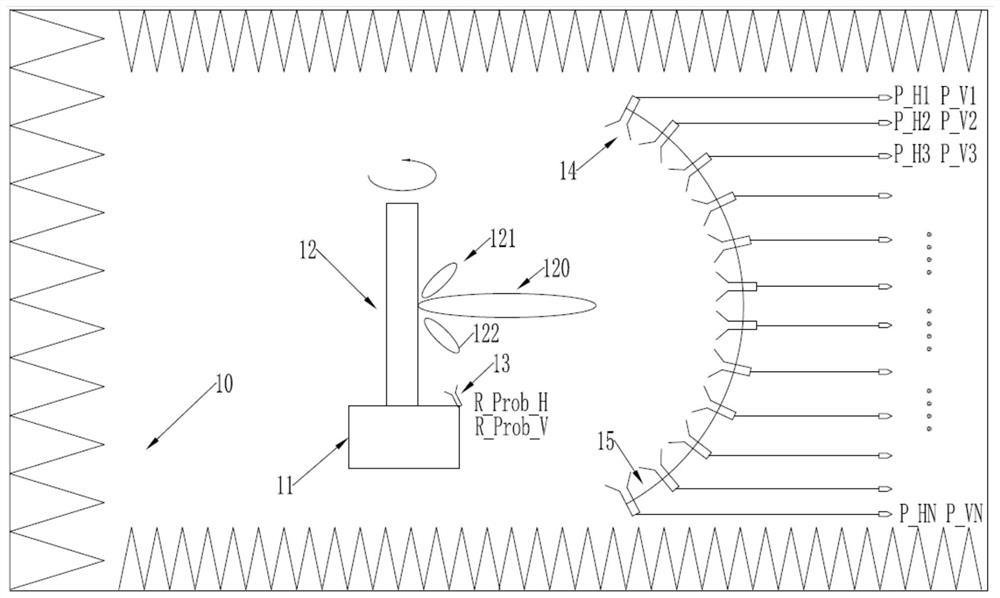
[0046] This embodiment is a phased array spurious emission test system, the system is composed as follows figure 1 shown.

[0047] The test field of this test system is a microwave anechoic chamber 10. The phased array antenna 12 used by the radio frequency transmitter to be tested is placed on a one-axis precision turntable 11. The one-axis precision turntable 11 can rotate with high resolution, and the near-field test requires a turntable. The arc length corresponding to the probe at the time of single-step rotation should be less than the half-wavelength corresponding to the highest frequency, that is:

[0048]

[0049] Where R is the radius of the arc probe array, and the antenna to be tested is placed at the center of the arc, It is the minimum step of single-axis turntable.

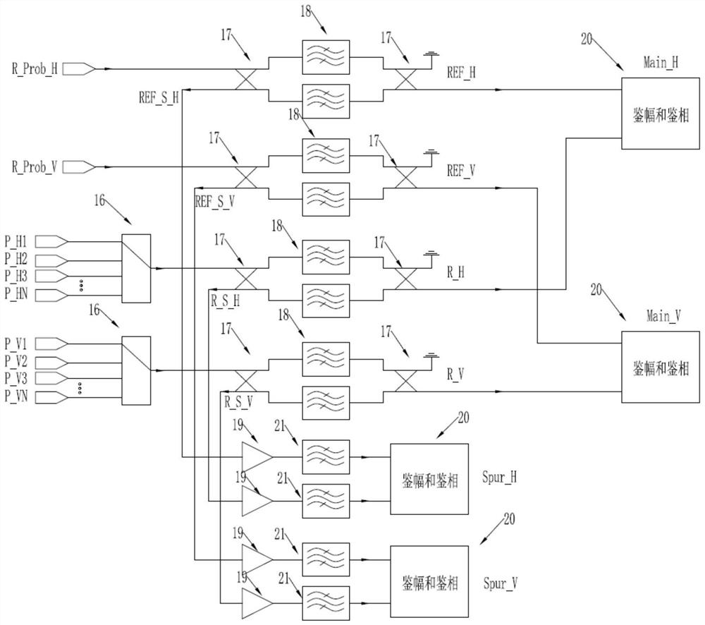
[0050] The radio frequency subsystem includes a vector network analyzer, and the vector network analyzer uses the test probe 14 to receive the radiation signal of the antenna of the radio freq...


PUM


Abstract

The invention provides a system and a method for testing stray radiation of a radio frequency transmitter. The system is a near-field test system, and a test field is a microwave anechoic chamber; a servo system is a one-axis precision rotary table installed in the microwave anechoic chamber, and an antenna of a radio frequency transmitter to be tested is arranged on the precision rotary table. Aradio frequency subsystem comprises a vector network analyzer. The vector network analyzer receives radiation signals of a radio frequency transmitter antenna to be tested through a test probe to complete amplitude and phase parameter test of the radio frequency transmitter antenna to be tested. The test method adopts a field test method. According to the invention, spherical near-field sampling of an electromagnetic field is realized by using a one-axis rotary table in cooperation with a probe array.

Description

technical field [0001] The invention relates to the field of stray radiation testing, in particular to a radio frequency transmitter stray radiation testing system and testing method. Background technique [0002] The complete communication transmitter includes a power transmitter and an antenna. At present, the transmitters and antennas of massive MIMO, active phased array radar, and the new generation of mobile communication base stations are all designed and produced in an integrated manner, and cannot be separated and tested separately. Adopt an over-the-air test method that can test the overall radiation performance. Modern RF transmitters often work in a wide frequency band, that is, they have multiple test frequency points; at the same time, each frequency point has multiple wave positions, that is, multiple radiation patterns are realized by phase control. At the same time, due to the nonlinearity of radio frequency devices and modules, additional spectrum signals w...

Claims


Application Information

Patent Timeline
Patent Type & Authority Applications(China)
IPC IPC(8): G01R29/10
CPCG01R29/105
Inventor 卜景鹏官国阳严方勇刘忠程
Owner GUANGDONG SHENGDA ELECTRONICS
Why Eureka
Try Eureka