Phase shifter

Active Publication Date: 2010-09-07
RENESAS ELECTRONICS CORP
View PDF10 Cites 12 Cited by
  • Summary
  • Abstract
  • Description
  • Claims
  • Application Information

AI Technical Summary

Benefits of technology

[0020]According to the embodiment of the present invention described above, it is possible to provide a phase shifter capable of generating output signals of havi

Problems solved by technology

However, phase shifter as disclosed in Japanese Unexamined Patent Publication Application Nos. 9-307414 and 8-237077 cannot adjust a duty ratio of the clock signal to 50% due to the added DC offset nor to keep a phase difference between output signals to 90 degrees if

Method used


Image

  • Phase shifter
  • Phase shifter
  • Phase shifter

Examples


first embodiment

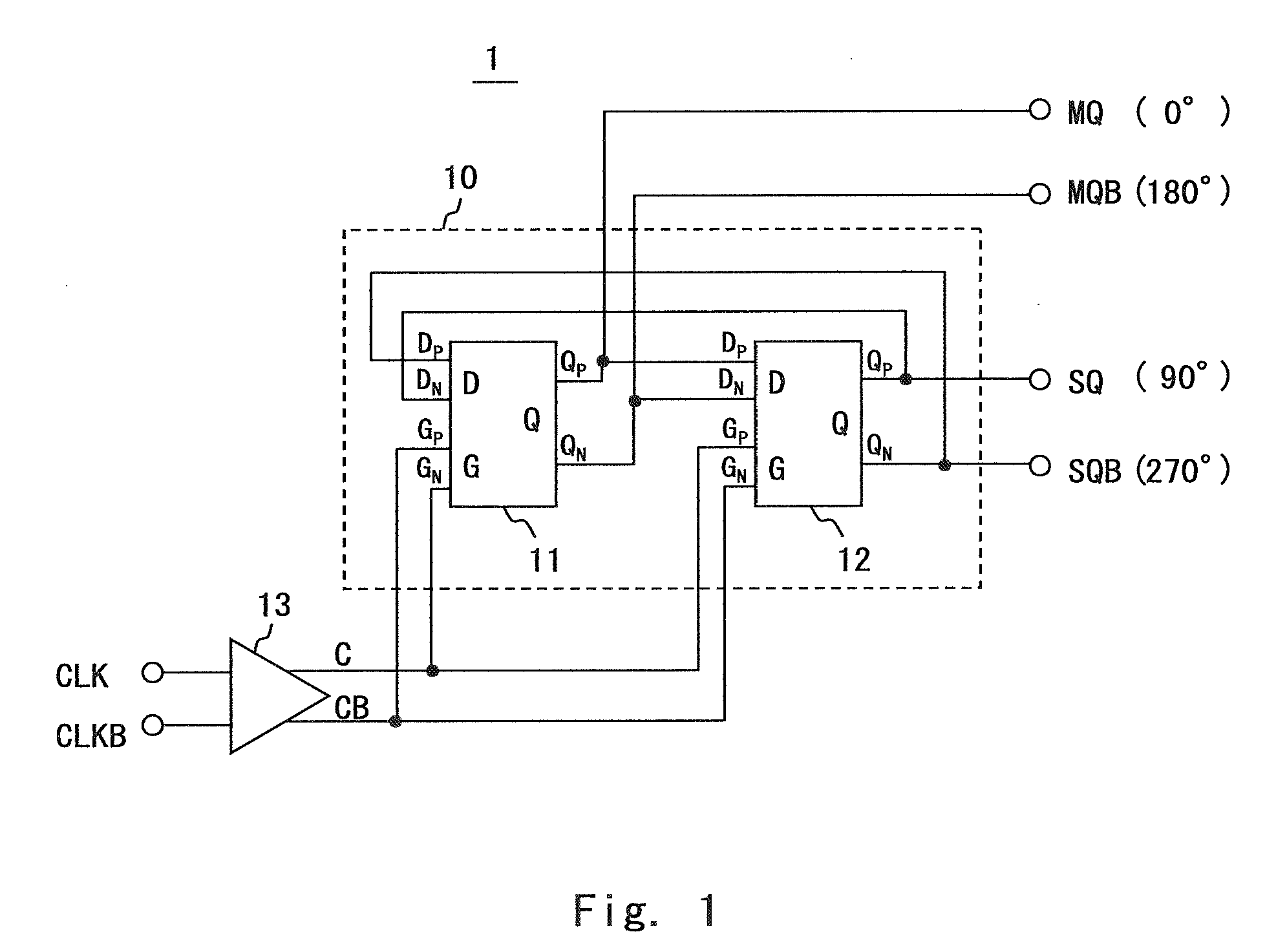
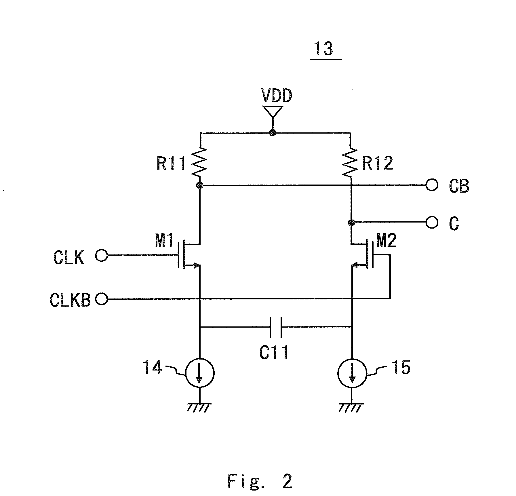
[0038]FIG. 1 shows the configuration of a phase shifter 1 of this embodiment. In FIG. 1, the dividing circuit 10 is a master-slave type T-flipflop where a master D latch 11 and a slave D latch 12 are connected in series. The basic configuration of the dividing circuit 10 is the same as that of the dividing circuit 70 of the phase shifter 70 of the related art. To be specific, an inverting Q output (QN) of the slave D latch 12 is feedback-connected to a D input (DP) of the master D latch 11. Further, a clock signal C obtained by filtering the input clock signal CLK through a high-pass filter (HPF) 13 as described hereinafter is input to a the G input (GP) of the slave D latch 12. On the other hand, an inverted clock signal CB obtained by filtering an inverting signal CLKB corresponding to the clock signal CLK through the HPF 13 is input to a the G input (GP) of the master D latch 11.

[0039]The master D latch 11 and the slave D latch 12 can be realized with various circuit configuratio...

second embodiment

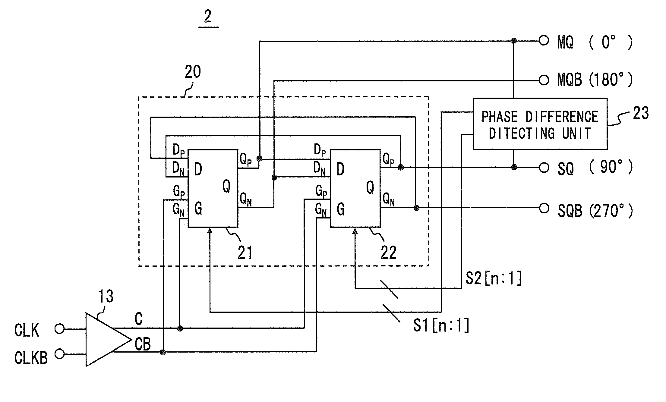
[0070]FIG. 9 shows the configuration of a phase shifter 2 of this embodiment. In FIG. 9, the dividing circuit 20 is a T-flip-flop type dividing circuit composed of a master D latches 21 and slave D latch 22 connected in tandem. The basic configuration of the dividing circuit 20 is the same as that of the dividing circuit 10 of the first embodiment. However, the master D latch 21 and slave D latch 22 include a variable capacitor with a variable capacitance function at output terminals.

[0071]A phase difference detecting circuit 23 detects a shift of a phase difference between the 0-degree signal output to the terminal MQ and the 90-degree signal output to the terminal SQ from 90 degrees. Further, the phase difference detecting circuit 23 outputs control signals S1 and S2 for changing a capacitance of the variable capacitor of the master D latch 21 and slave D latch 22 in accordance with the detected shift of the phase difference. Incidentally, in this embodiment, the control signals S...


PUM


Abstract

A phase shifter according to an embodiment of the present invention includes: an AC component amplifying unit; and a dividing circuit. The AC component amplifying unit has positive gain slope characteristics and deforms a waveform of an input differential clock signal to output the deformed differential clock signal. The dividing circuit includes a T-flipflop having two D latches connected in series and receives the deformed differential clock signal defoemed by the AC component amplifying unit to generate at least two output signals having a phase difference of 90 degrees with a frequency of ½ of the deformed differential clock signal.

Description

BACKGROUND OF THE INVENTION[0001]1. Field of the Invention[0002]The present invention relates to a phase shifter that divides a frequency of an input signal to generate output signals 90 degrees out of phase with each other.[0003]2. Description of Related Art[0004]FIG. 11 shows the configuration of a phase shifter of the related art A phase shifter 7 of FIG. 11 receives differential clock signals, more specifically, a clock signal CLK and an inverted clock signal CLKB complementary to the clock signal CLK, divides frequencies of the signals by 2, and outputs four signals having a phase difference of 90 degrees to terminals MQ, MQB, SQ and SQB.[0005]A dividing circuit (dividing circuit) 70 of the phase shifter 7 is configured by a master-slave type flipflop (MS-FF) where a master D latch 71 and a slave D latch 72 are connected in series. Further, an inverting Q output (QN) of the slave D latch 72 is feedback-connected to a D input (DP) of the master D latch 71, a clock signal CLK is ...

Claims


Application Information

Patent Timeline
IPC IPC(8): H03K5/13H03K5/135
CPCH03K5/1565H03K2005/00052H03K2005/00286H03L7/0812
Inventor KUROKI, REIKO
Owner RENESAS ELECTRONICS CORP
Why Eureka
Try Eureka