Improved self-mix module utilizing filters

a filter and self-mixing technology, applied in the field of signal processing and to sensors, can solve the problems of low achievable signal level, insufficient degree of improvement for a number of interesting consumer applications, and many of the limitations of traditional lasers, so as to reduce increase the apparent peak-to-peak modulation of the signal, and reduce the effect of apparent peak-to-peak modulation

Inactive Publication Date: 2019-10-31
VIXAR +1
View PDF3 Cites 9 Cited by
  • Summary
  • Abstract
  • Description
  • Claims
  • Application Information

AI Technical Summary

Benefits of technology

[0013]The purpose of the filter is to provide a signal to the detector that is very sensitive to the wavelength of the sampled laser beam such that very small changes in wavelength cause large changes in transmission or reflection characteristics of the filter. In other words, the probability of a photon in the sampled self-mix modulated light reaching the detector after encountering the filter depends strongly on its wavelength. Since it is in the physical nature of self-mixing signals to exhibit wavelength modulation in time synchronicity with amplitude or intensity modulation, the filter can act to as to effectively amplify or suppress the signal available for detection.
[0014]The laser may be operated such that the wavelength of the emitted light corresponds to a region of relatively steep change in the filter transmission or reflection characteristics. If operating on a rising edge of the filter characteristic, where the transmission or reflection is increasing as wavelength is increasing, and the increase in the intensity of the sampled light signal is accompanied by a shift to longer wavelength, the effect is additive (in phase) and the apparent peak-to-peak modulation of the signal will be increased. If operating on a falling edge of the filter characteristic, where the transmission or reflection is decreasing as wavelength is increasing, and the increase in the intensity of the sampled light signal is accompanied by a shift to longer wavelength, the effect is subtractive (out of phase) and the apparent peak-to-peak modulation of the signal will be reduced. If operating on a rising edge of the filter characteristic, where the transmission or reflection is increasing as wavelength is increasing, and the increase in the intensity of the sampled light signal is accompanied by a shift to shorter wavelength, the effect is subtractive (out of phase) and the apparent peak-to-peak modulation of the signal will be reduced. If operating on a falling edge of the filter characteristic, where the transmission or reflection is decreasing as wavelength is increasing, and the increase in the intensity of the sampled light signal is accompanied by a shift to shorter wavelength, the effect is additive (in phase) and the apparent peak-to-peak modulation of the signal will be increased.
[0015]In principle, this aspect of various embodiments disclosed herein will work with all kinds of lasers where the self-mixing effect can occur. Various embodiments disclosed herein can be employed in a system using a beam splitter to sample the laser light that is not directed towards the target. Embodiments disclosed herein can likewise be used in a system where the sampled portion of the laser light is derived from emission from the back facet in the case of an edge-emitting laser or the substrate surface in the case of a VCSEL. It is also possible that the filter element can serve a dual function as both the filter and the beam sampling component, i.e. the beam-splitter.
[0016]A further aspect of various embodiments disclosed herein is the reduction of packaging size and complexity by using a substrate-emitting VCSEL laser. Typical VCSELs are designed with a very high reflectivity bottom mirror (>99.9%), and as such almost all of the optical power is emitted through the top surface mirror with a lower reflectivity, typically <99.6%. By reducing the reflectivity of the bottom mirror, the amount of laser light emitted through the substrate can increase. If the VCSEL is then mounted in a position above the detector, this bottom-emitted light is available for monitoring the self-mix signal. Thus, the need for a beam splitter is removed. The VCSEL can be stacked directly on the detector or set at a distance with an intermediate air gap. The partially bottom emitting VCSEL is advantageous for packaging with an etalon. Preferably, the VCSEL has patterned metal on the substrate side with holes or apertures which serve to let the laser light pass while suppressing unwanted spontaneous emission light. The presence of spontaneous emission at the detector can cause an unwanted detector signal that degrades the signal-to-noise ratio. The substrate emitting surface may also be coated with a low-reflectivity coating to reduce signal loss, improve linearity of the laser power emission as a function of injected current, and reduce or minimize perturbations to the laser cavity light itself.
[0017]To further reduce sensor size, cost, and packaging complexity while improving performance, embodiments disclosed herein may utilize a VCSEL laser directly integrated with an etalon. The VCSEL, being in part comprised of a highly reflective mirror adjacent to an optically transparent substrate, can incorporate the etalon filtering functionality by coating the substrate final surface with a highly-reflective (HR) mirror coating. In such case the substrate is itself the cavity spacer region of the etalon, bounded on one side by the VCSELs bottom DBR and by the HR coating on the other. Due to the divergence of the beam and the small beam diameter of the laser illumination within the etalon cavity, the expected performance may not be ideal, but may prove adequate to yield significant signal enhancement.

Problems solved by technology

However, VCSELs suffer from many of the same limitations as traditional lasers, namely the low achievable signal levels.
Work has been done to optimize VCSELs for improving VCSEL self-mixing performance, but the degree of improvement is still not adequate for a number of interesting consumer applications envisioned here.

Method used


Image

  • Improved self-mix module utilizing filters
  • Improved self-mix module utilizing filters
  • Improved self-mix module utilizing filters

Examples


Embodiment Construction

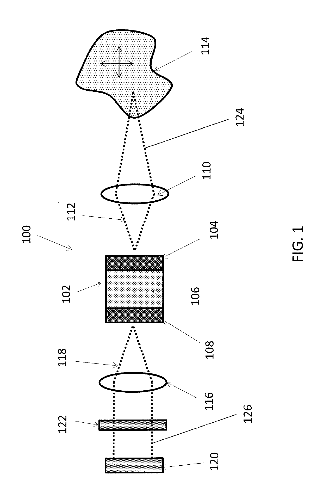
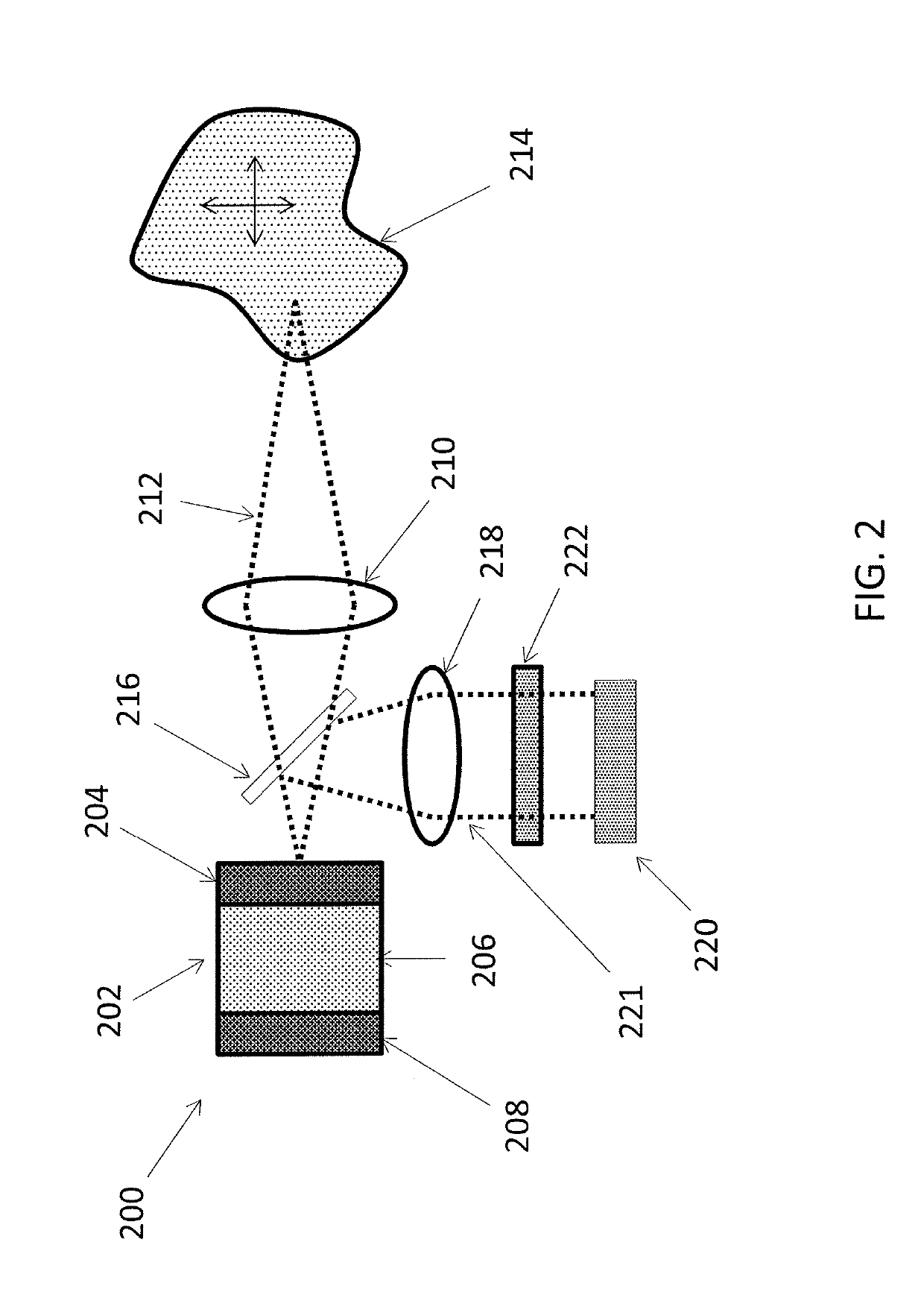
[0042]The present disclosure relates to processing of signals and to sensors based on the mechanism of laser self-mixing, as well as packaging for the sensor.

[0043]In the following detailed description, numerous specific details are set forth in order to provide a thorough understanding of some embodiments. However, it will be understood by persons of ordinary skill in the art that some embodiments may be practiced without these specific details. In other instances, well-known methods, procedures, components, units and / or circuits have not been described in detail so as not to obscure the discussion.

[0044]Functions, operations, components and / or features described herein with reference to one or more embodiments of the present disclosure, may be combined with, or may be utilized in combination with, one or more other functions, operations, components and / or features described herein with reference to one or more other embodiments of the present disclosure. The present disclosure may...


PUM


Abstract

A system and method for generating, enhancing, and detecting the amplitude and phase modulation of a laser under a condition of self-mixing is provided. The system may comprise a laser and a detector to extract the characteristic self-mix signal, which is then interpreted using algorithms implemented in hardware or software. In the case of the laser being a Vertical Cavity Surface Emitting laser (VCSEL), the output signal can be detected by monitoring the surface light emission by means of a beam splitter, or in some embodiments as emission from the bottom surface of the laser. In some embodiments, the system may further comprise a wavelength filter such as an etalon in the signal path.

Description

CROSS-REFERENCE TO RELATED APPLICATIONS[0001]This application claims the benefit of and priority from U.S. Prov. Pat. Appl. No. 62 / 349,123, titled “Improved Self-Mix Module Utilizing Filters,” filed Jun. 13, 2016, the contents of which are hereby incorporated by reference herein in their entirety.FIELD OF THE INVENTION[0002]The present invention disclosure is related to processing of signals and to sensors based on the mechanism of laser self-mixing. Also disclosed are means for improved packaging for the sensors.BACKGROUND OF THE INVENTION[0003]The background description provided herein is for the purpose of generally presenting the context of the disclosure. Work of the presently named inventors, to the extent it is described in this background section, as well as aspects of the description that may not otherwise qualify as prior art at the time of filing, are neither expressly nor impliedly admitted as prior art against the present disclosure.[0004]Self-mixing, or optical feedbac...

Claims


Application Information

Patent Timeline
Patent Type & Authority Applications(United States)
IPC IPC(8): G01B9/02H01S5/026H01S5/022H01S5/183G02B27/30G01S17/32H01S5/0239
CPCG01B9/02092H01S2301/02G01B2290/25H01S5/18305H01S5/0262H01S5/02252G01B9/02015G02B27/30H01S5/00H01S5/183G01S17/32G01S17/50G01B9/0205G01S7/4814H01S5/0028G01S7/4916H01S5/02253H01S5/0239H01S5/02326
Inventor JOHNSON, KLEINFISHMAN, TALBAKISH, TAL
Owner VIXAR
Why Eureka
Try Eureka