Digitally controlled circuit for reducing the phase modulation of a signal

a digital control circuit and signal technology, applied in the field of digital control circuits, to achieve the effect of reducing the phase modulation of the signal

Inactive Publication Date: 2005-04-05
LANTIQ BET GMBH & CO KG
View PDF7 Cites 16 Cited by
  • Summary
  • Abstract
  • Description
  • Claims
  • Application Information

AI Technical Summary

Benefits of technology

It is accordingly an object of the invention to provide a digitally controlled circuit for reducing the phase modulation of a signal that overcomes the above-mentioned disadvantages of the prior art devices of this general type, which generates a clock that is free of phase modulation (which has no jitter) digitally and without using any external components, and which can follow a dynamic change in the frequency precisely.
The sigma-delta modulator for suppressing the phase modulation may, in a particularly advantageous and simple manner, be in the form of a binary adder that adds the values coming from the phase comparator. The overflow and underflow outputs of the adder can then be used directly for producing the correction commands.

Problems solved by technology

However, in the past, such modulators have been used in the prior art only for recovering non-integer fractions of frequencies.

Method used


Image

  • Digitally controlled circuit for reducing the phase modulation of a signal
  • Digitally controlled circuit for reducing the phase modulation of a signal
  • Digitally controlled circuit for reducing the phase modulation of a signal

Examples


Embodiment Construction

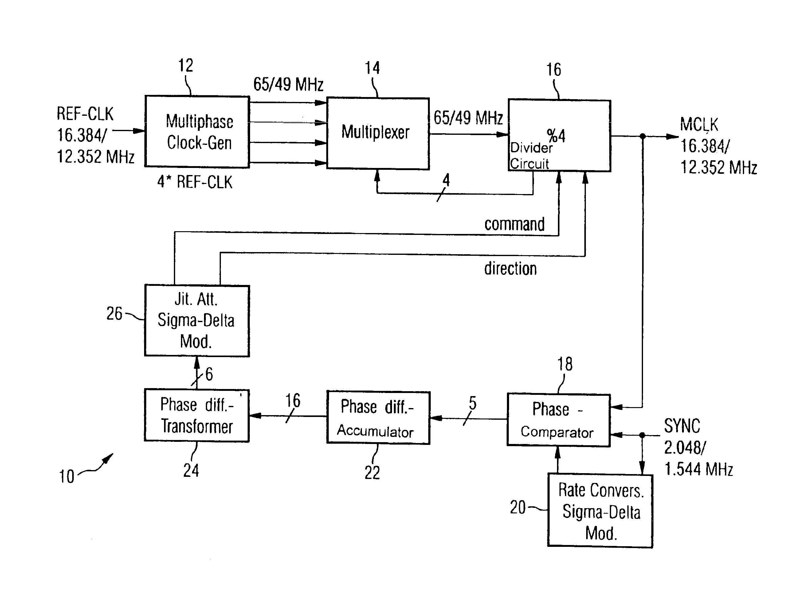
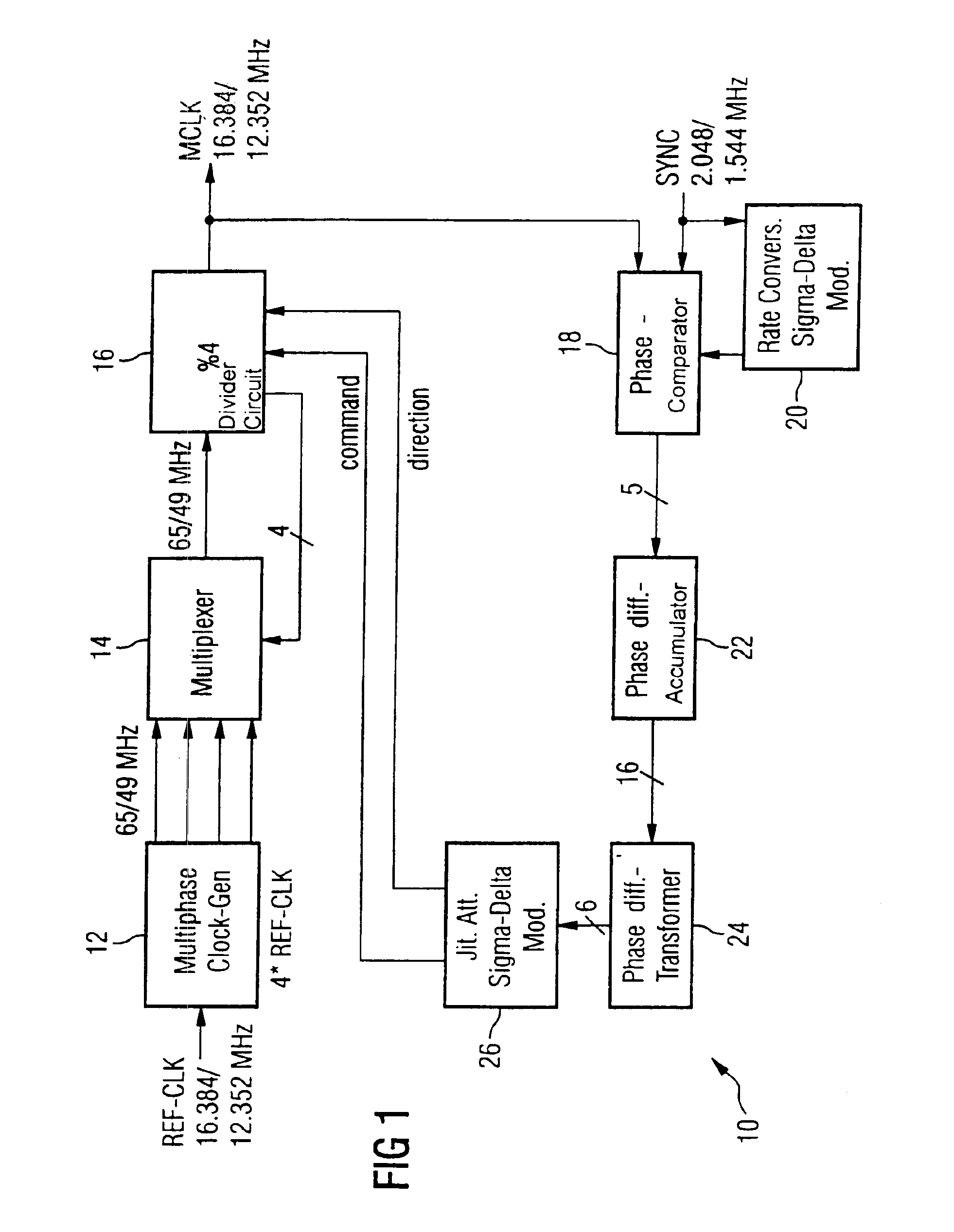
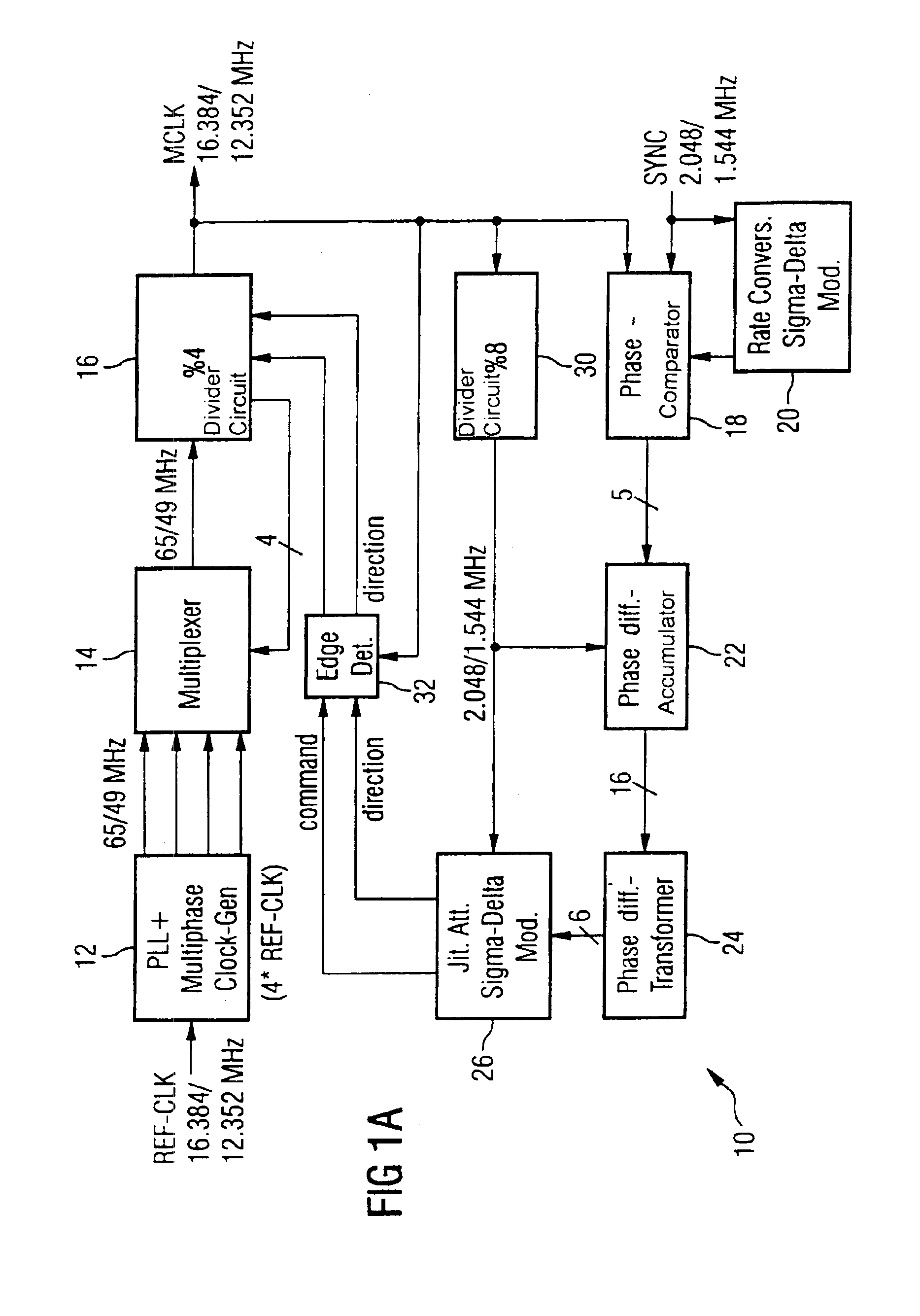
In all the figures of the drawing, sub-features and integral parts that correspond to one another bear the same reference symbol in each case. Referring now to the figures of the drawing in detail and first, particularly, to FIG. 1 thereof, there is shown an outline block diagram of a digitally controlled circuit according to the invention for reducing phase modulation of a signal, including a clock-rate conversion using a sigma-delta modulator. A jittered input signal SYNC is in this case compared with a master clock MCLK. The latter at the same time represents the output signal of the circuit. A determined phase difference is integrated in a sigma-delta modulator. The principle of sigma-delta modulators is based on phase-error accumulation. A phase error between the MCLK and the MCLK required by the control system is recalculated and at the same time evaluated in each basic clock cycle. The aim is thus to generate the clock MCLK which has no jitter, digitally and without using any...


PUM


Abstract

A digitally controlled circuit for reducing the phase modulation of a signal. The circuit has a multiphase clock generator that produces n phases of a clock that is m-times the signal. The circuit further has a multiplexer with n inputs for the n phases of the clock and with one output which supplies the output signal. The output signal and the signal are connected to the inputs of a phase comparator. The output signal of the comparator is supplied to a sigma-delta modulator whose output signals are used for controlling the multiplexer. A jittered input signal is compared in the phase comparator with a master clock. The determined phase difference is integrated in a sigma-delta modulator. The aim of the circuit is to generate a clock without jitter, digitally and without using external components. This circuit provides 20 dB / decade attenuation of the jitter received in the SYNC signal, based on the P-regulator characteristic.

Description

BACKGROUND OF THE INVENTIONField of the InventionThe present invention relates to a digitally controlled circuit for reducing phase modulation (jitter) of a signal. The present circuit allows clock-rate conversion to be carried out at the same time.The phase modulation of a signal is normally referred to as “jitter” in the specialist terminology. The jitter is generally sinusoidal and is defined by a jitter frequency and a jitter amplitude.As far as possible, digital signal processing attempts to manage jitter control without using any analog components. In particular, the aim is to be able to form the circuits completely in an integrated circuit, without any external components. Circuits for reducing the phase modulation (jitter attenuators) according to the prior art normally require external components. This results in additional technological and temperature relationships, and non-linearities in the external components. At the same time, more space is consumed on the board, and ...

Claims


Application Information

Patent Timeline
Patent Type & Authority Patents(United States)
IPC IPC(8): H03L7/093H03L7/081H03L7/099H03L7/08H04J3/06
CPCH03L7/0814H04J3/0626H03L7/0991H03L7/093
Inventor PITZER, ARMINHINZ, TORSTEN
Owner LANTIQ BET GMBH & CO KG
Why Eureka
Try Eureka