Auxiliary welding tool clamp

A tooling fixture and auxiliary welding technology, which is applied in the field of welding tooling fixtures, can solve the problems of low production efficiency and large manpower consumption, and achieve the effects of improving welding efficiency, friction, welding precision and accurate size

Inactive Publication Date: 2020-10-02
SHANGHAI KONGBO IND
View PDF6 Cites 0 Cited by
  • Summary
  • Abstract
  • Description
  • Claims
  • Application Information

AI Technical Summary

Problems solved by technology

[0002] Welding is used more and more widely in all walks of life. In the welding production process, for a relatively large and heavy workpiece, and when all four sides need to be welded, it is generally moved and turned manually during the welding production process. Not only does it need to It consumes a lot of manpower and the production efficiency is very low

Method used


Image

  • Auxiliary welding tool clamp
  • Auxiliary welding tool clamp
  • Auxiliary welding tool clamp

Examples


Embodiment 1

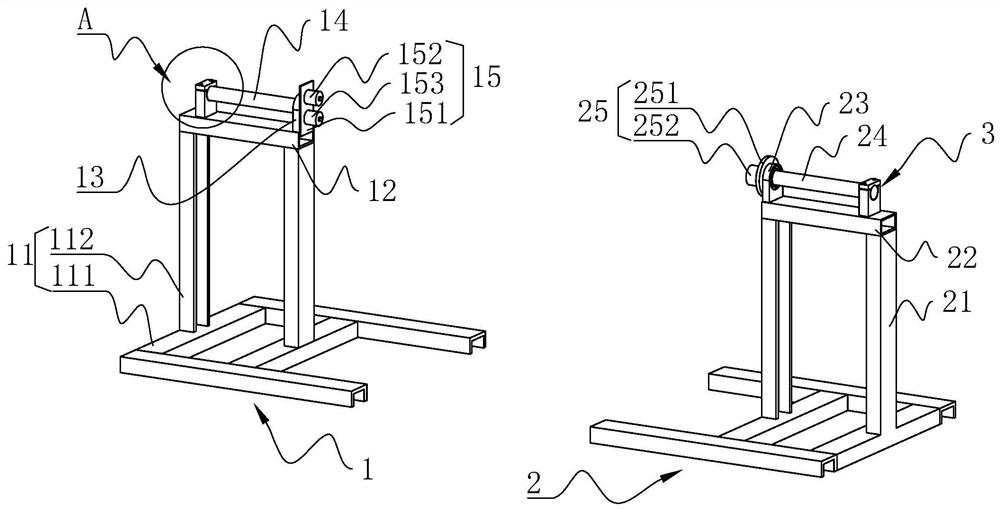
[0034] Reference figure 1 with figure 2 , An auxiliary welding fixture, comprising a left support assembly 1 and a right support assembly 2. The left support assembly 1 includes a left support frame 11, the left support frame 11 is welded with a cuboid-shaped left mounting plate 12, and the left mounting plate 12 is welded There is a left bearing seat 13, a first rotating shaft 14 is installed in the left bearing seat 13, and one end of the first rotating shaft 14 close to the right support assembly 2 is fixedly provided with a first clamping portion 15 for clamping with a welding tool.

[0035] The right support assembly 2 includes a right support frame 21, a rectangular right mounting plate 22 is welded on the right support frame 21, a right bearing seat 23 is welded to the right mounting plate 22, and a second rotating shaft 24 is rotatably installed in the right bearing seat 23 , An end of the second rotating shaft 24 close to the left support assembly 1 is fixedly provided w...

Embodiment 2

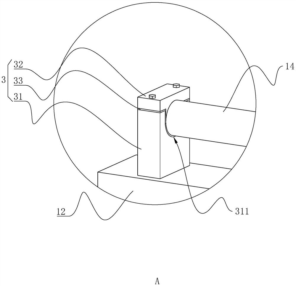
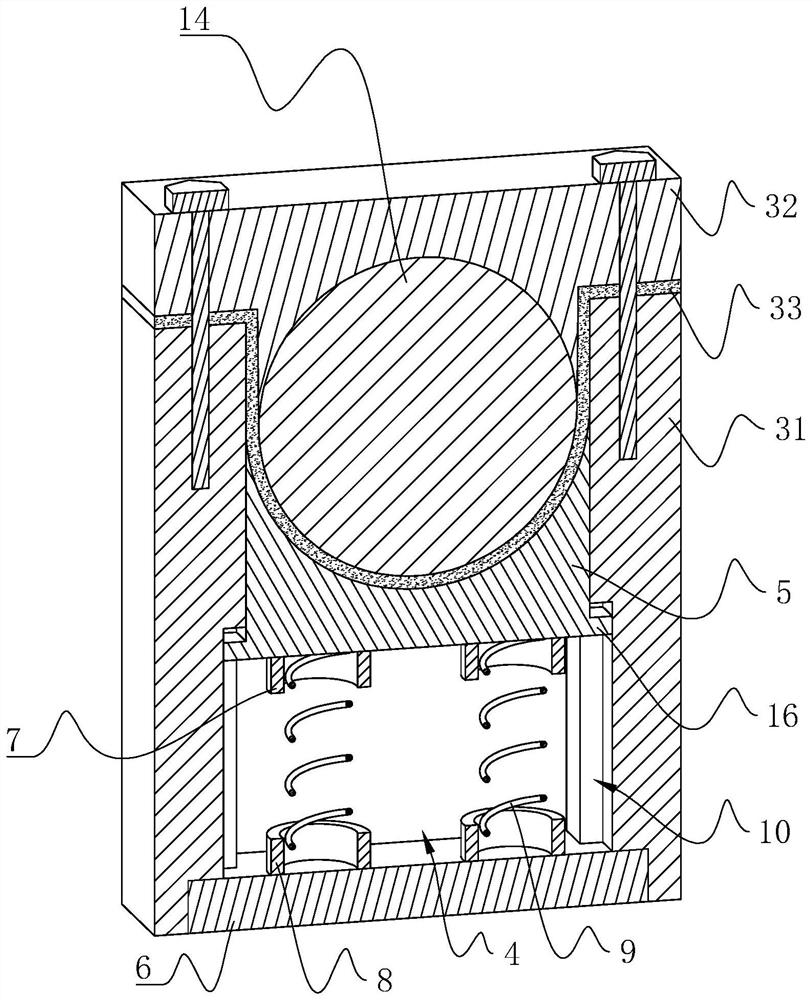
[0043] Reference figure 1 with image 3 The difference between this embodiment and embodiment 1 is that the support block 31 is mounted on the left mounting plate 12 and the right mounting plate 22 by bolts, and the support block 31 is provided with a square chute 4 at one end away from the support groove 311, The bottom of the sliding groove 4 is in communication with the supporting groove 311, a square clamping block 5 is slidably installed in the sliding groove 4, the clamping block 5 abuts against the damping block 33, and the end of the clamping block 5 and the damping block 33 In cooperation, a cuboid-shaped end sealing plate is installed at the notch of the sliding groove 4 through bolts.

[0044] An end of the tightening block 5 close to the end sealing plate is formed with an annular upper ring sleeve 7, and an end of the end sealing plate close to the tightening block 5 is formed with a lower ring sleeve 8 having the same shape as the upper ring sleeve 7. A tightening s...


PUM


Abstract

The invention relates to an auxiliary welding tool clamp. The auxiliary welding tool clamp comprises a left supporting assembly and a right supporting assembly, wherein the left supporting assembly comprises a left supporting frame, a left mounting plate is arranged on the left supporting frame, a first rotating shaft is rotationally mounted on the left mounting plate, and a first clamping part isfixedly arranged at one end of the first rotating shaft; the right supporting assembly comprises a right supporting frame, a right mounting plate is arranged on the right supporting frame, a second rotating shaft is rotationally mounted on the right mounting plate, and a second clamping part is fixedly arranged at one end of the second rotating shaft; pressing parts used for pressing the first rotating shaft and the second rotating shaft are arranged on the left mounting plate and the right mounting plate correspondingly, and each pressing part comprises a supporting block, a fixing block anda damping block; and the supporting blocks are fixedly arranged on the left mounting plate and the right mounting plate correspondingly, supporting grooves are formed in the supporting blocks, the damping blocks are mounted in the supporting grooves, and the fixing blocks are connected with the supporting blocks through bolts and press the rotating shafts. The auxiliary welding tool clamp has theadvantages of being convenient to weld, capable of saving labor and high in welding precision and size.

Description

Technical field [0001] This application relates to the field of welding tooling and fixtures, in particular to an auxiliary welding tooling fixture. Background technique [0002] Welding is used more and more widely in all walks of life. In the welding production process, for relatively large and heavy workpieces, and when all four sides need to be welded, the welding production process is generally moved and flipped manually. It consumes a lot of manpower and the production efficiency is very low. Therefore, a new solution is needed to solve the above-mentioned problems. Summary of the invention [0003] In order to improve the welding efficiency, this application provides an auxiliary welding fixture. [0004] The auxiliary welding tooling fixture provided in this application adopts the following technical solutions: [0005] An auxiliary welding tooling fixture, comprising a left support assembly and a right support assembly, the left support assembly includes a left support fra...

Claims


Application Information

Patent Timeline
Patent Type & Authority Applications(China)
IPC IPC(8): B23K37/047B23K37/04
CPCB23K37/04B23K37/0443B23K37/047
Inventor 许光荣苏斌
Owner SHANGHAI KONGBO IND
Why Eureka
Try Eureka