
Electric power accessory manufacturing batch assembling machine and manufacturing assembling method

A mass-produced, assembling machine technology, applied in the direction of manufacturing tools, metal processing, metal processing equipment, etc., can solve problems such as inability to lock bolts and nuts, low device convenience, and inability to achieve rapid unloading.

Inactive Publication Date: 2020-10-09
林瑞
View PDF6 Cites 4 Cited by
  • Summary
  • Abstract
  • Description
  • Claims
  • Application Information

AI Technical Summary

Problems solved by technology

[0003] However, the current mass assembly machines for electric power parts production in the market have the following problems during use. Realize the locking between bolts and nuts, and cannot realize the automatic replenishment of nuts; b. After the existing batch assembly machines for electric power accessories are assembled, the assembled parallel hanging plates are still in the assembly mechanism , it needs to be taken manually, which leads to low overall convenience of the device and cannot realize fast unloading

Method used


Image

  • Electric power accessory manufacturing batch assembling machine and manufacturing assembling method
  • Electric power accessory manufacturing batch assembling machine and manufacturing assembling method
  • Electric power accessory manufacturing batch assembling machine and manufacturing assembling method

Examples


Embodiment Construction

[0034] In order to make the technical problems, technical solutions and beneficial effects to be solved by the present invention clearer, the present invention will be further described in detail below in conjunction with the accompanying drawings and embodiments. It should be understood that the specific embodiments described here are only used to explain the present invention, not to limit the present invention.

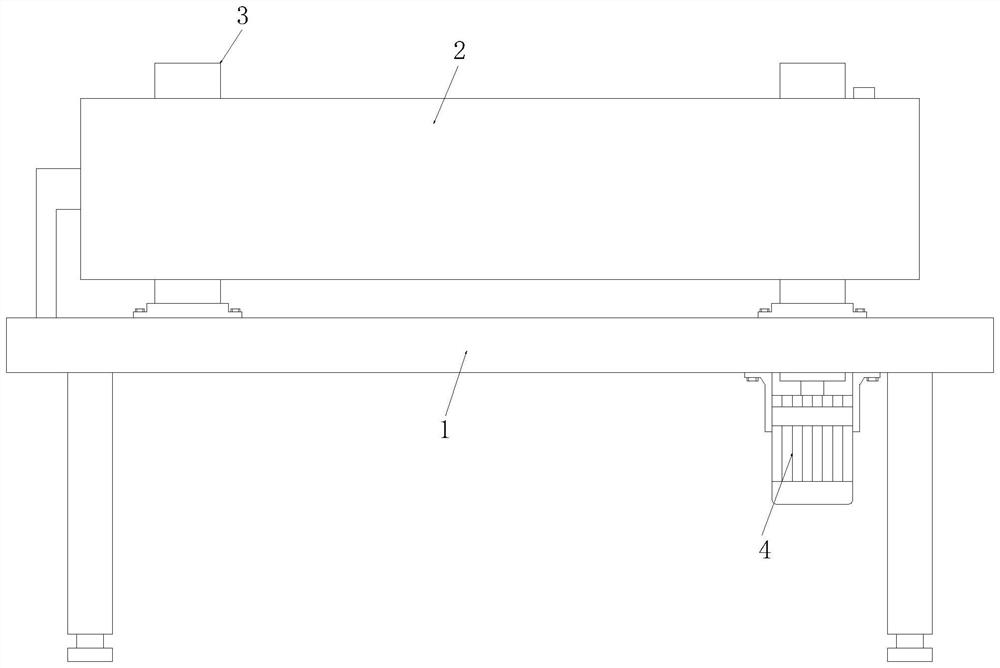
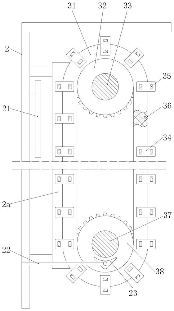
[0035] Such as Figure 1 to Figure 9 As shown, a batch assembly machine for producing electric accessories includes a worktable 1, a protective shell 2, an assembly mechanism 3 and a drive motor 4, the upper end of the worktable 1 is equipped with a protective shell 2 through a fixing frame, and the protective shell 2 An assembly mechanism 3 is arranged inside, and a drive motor 4 is installed on the bottom of the worktable 1 through a motor fixing frame, and the drive motor 4 is connected to the assembly mechanism 3;

[0036] The inner wall of the protective shel...


PUM


Abstract

The invention discloses an electric power accessory manufacturing batch assembling machine and a manufacturing assembling method. The batch assembling machine comprises a working table top, a protective shell, an assembling mechanism and a driving motor, wherein the protective shell is installed at the upper end of the working table top through a fixing frame, the assembling mechanism is arrangedin the protective shell, the driving motor is mounted at the bottom of the working table through a motor fixing frame and connected with the assembling mechanism, a rectangular plate is arranged on the inner wall of the protective shell, a supporting plate is welded to the top of the protective shell, a connecting rod is welded to one end of the protective shell, a triangular plate is connected tothe bottom of the connecting rod, a driven shaft and a driving shaft are installed on the working table through shaft seats, a round hole is formed in the joint of the interior of the working table and the driving shaft, the driving shaft penetrates through the round hole to be connected with an output shaft of the driving motor, a driven synchronizing wheel is installed on the outer wall of thedriven shaft, and a driving synchronizing wheel is installed on the outer wall of the driving shaft. According to the batch assembling machine, automatic locking of a bolt and a nut and automatic separation of parallel hanging plates can be rapidly completed.

Description

technical field [0001] The invention relates to the technical field of electric power accessories assembly machinery, in particular to a batch-production assembly machine and a production and assembly method for electric power accessories. Background technique [0002] Iron or aluminum metal accessories widely used in power transmission lines are collectively referred to as power accessories. Most of the power accessories need to bear a large pulling force during operation, and some have to ensure good electrical contact at the same time. There are many types of power accessories with different uses, for example, various clamps for installing wires, various hanging rings and various parallel hanging plates for forming insulator strings. Among them, the usage of parallel hanging boards is the highest. The structure of the parallel hanging plate is relatively simple, which is composed of a flat plate, bolts and nuts, and is often assembled by assembly. [0003] However, the...

Claims


Application Information

Patent Timeline
Patent Type & Authority Applications(China)
IPC IPC(8): B23P19/06
CPCB23P19/001B23P19/06
Inventor 林瑞
Owner 林瑞
Learn More