Temporary lighting equipment for engineering construction

A temporary lighting and engineering technology, applied in lighting and heating equipment, lighting applications, mechanical equipment, etc., can solve the problems of fixed lighting range, removal of lighting, inconvenience, etc., to avoid adjusting the direction of the vehicle, easy to adjust the angle, Energy saving effect

Inactive Publication Date: 2020-10-13
安徽巨华建设工程科技有限公司
View PDF0 Cites 2 Cited by
  • Summary
  • Abstract
  • Description
  • Claims
  • Application Information

AI Technical Summary

Problems solved by technology

[0002] Lighting is a measure to use various light sources to illuminate working and living places or individual objects. In engineering construction, in order to meet the needs of outdoor construction at night, it is necessary to place temporary lighting equipment. However, the commonly used temporary lighting equipment now has fixed lamps and is inconvenient to adjust. The lamp angle and lighting range are relatively fixed, and when the lighting direction needs to be adjusted, the direction of the vehicle needs to be adjusted, which is very inconvenient. The lamp is single and cannot be removed for lighting alone. This invention proposes a new solution to the above problems

Method used


Image

  • Temporary lighting equipment for engineering construction
  • Temporary lighting equipment for engineering construction
  • Temporary lighting equipment for engineering construction

Examples


Embodiment Construction

[0025] In order to make the technical solutions of the present invention clearer and clearer to those skilled in the art, the present invention will be further described in detail below in conjunction with the examples and accompanying drawings, but the embodiments of the present invention are not limited thereto.

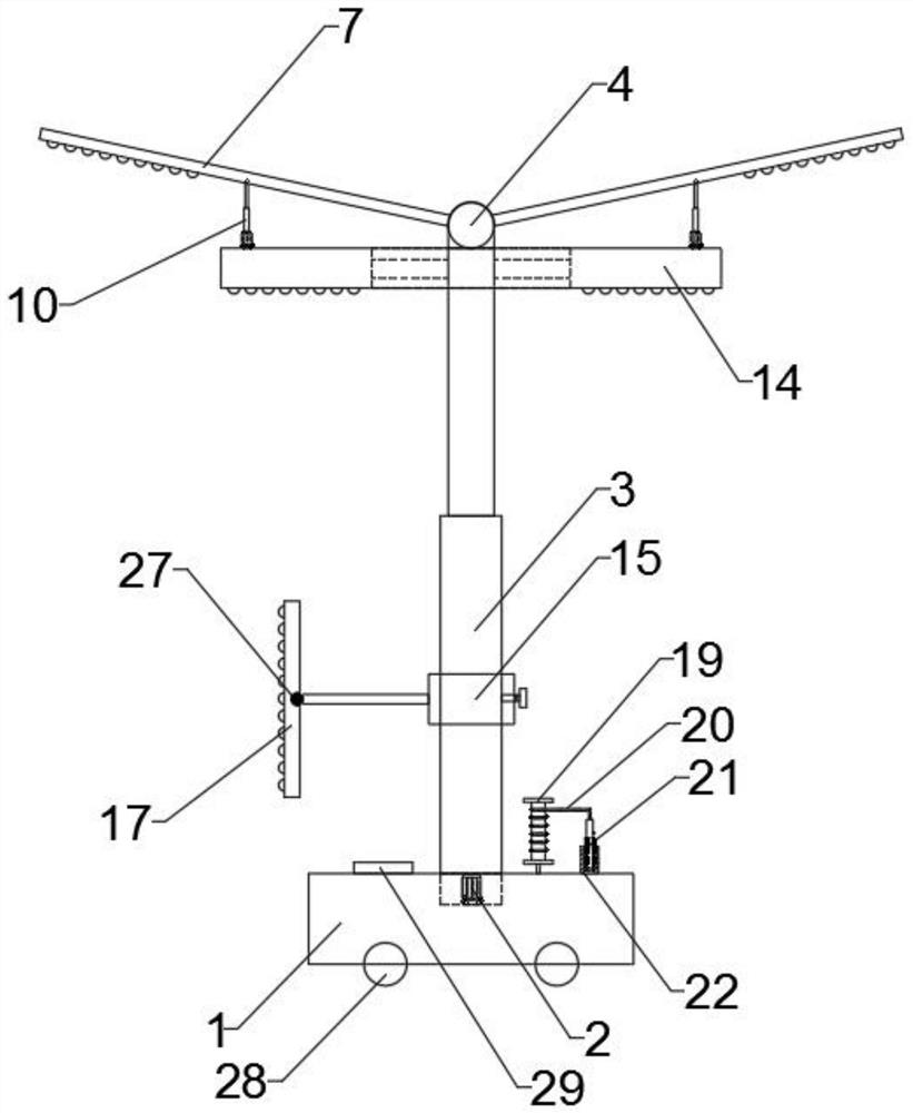
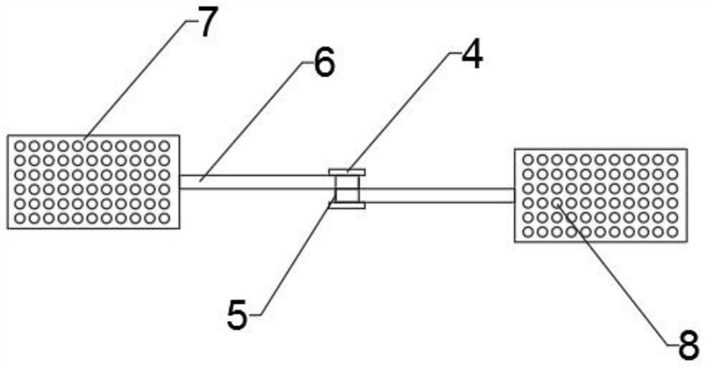
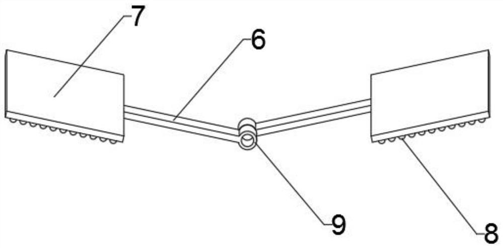
[0026] Such as Figure 1-Figure 7 As shown, the temporary lighting equipment used in engineering construction provided by this embodiment includes a mobile base 1 and a motor 2 disposed inside the mobile base 1. The output shaft of the motor 2 passes through the mobile base 1 and is connected to an electric telescopic column 3. The telescopic column 3 fixes the second lamp 14 outside the electric telescopic column 3 through a plurality of connecting plates 13. The top of the electric telescopic column 3 is provided with two limiting plates 4, and a rotating shaft 5 is arranged between the two limiting plates 4. , both sides of the rotating shaft 5 are provided with...


PUM


Abstract

The invention discloses temporary lighting equipment for engineering construction. The invention belongs to the technical field of engineering lighting equipment. The temporary lighting equipment comprises a movable base and a motor arranged in the movable base, an output shaft of the motor penetrates through the movable base to be connected with an electric telescopic column, the electric telescopic column is fixedly arranged on a second lamp outside the electric telescopic column through a plurality of connecting plates, two limiting plates are arranged at the top of the electric telescopiccolumn, a rotating shaft is arranged between the two limiting plates, and first lamps are arranged on the two sides of the rotating shaft. An annular light source with the adjustable height is adoptedfor illumination, so that the illumination range is adjustable, illumination is uniform, and energy is saved; the lighting ranges of the first lamps can be adjusted through angle adjusting devices, the direction of a third lamp can be adjusted through a positioning bolt, and the direction of the whole vehicle is prevented from being adjusted; a magnet is attracted to a second connecting rod, andthe angle is convenient to adjust; and a movable lamp can be independently taken down for lighting, and the various lamps can meet different lighting requirements of engineering construction.

Description

technical field [0001] The invention relates to engineering lighting equipment, in particular to a temporary lighting equipment used in engineering construction, and belongs to the technical field of engineering lighting equipment. Background technique [0002] Lighting is a measure to use various light sources to illuminate working and living places or individual objects. In engineering construction, in order to meet the needs of outdoor construction at night, it is necessary to place temporary lighting equipment. However, the commonly used temporary lighting equipment now has fixed lamps and is inconvenient to adjust. The lamp angle and lighting range are relatively fixed, and when the lighting direction needs to be adjusted, the direction of the vehicle needs to be adjusted, which is very inconvenient. The lamp is single and cannot be removed for lighting alone. The present invention proposes a new solution to the above problems. [0003] How to develop a kind of temporar...

Claims


Application Information

Patent Timeline
Patent Type & Authority Applications(China)
IPC IPC(8): F21S6/00F21V21/06F21V21/15F21V21/22F21V21/26F21V21/36F21V21/096F21W131/402
CPCF21S6/006F21V21/06F21V21/096F21V21/15F21V21/22F21V21/26F21V21/36F21W2131/402
Inventor 王祥
Owner 安徽巨华建设工程科技有限公司
Why Eureka
Try Eureka