
Optical device, display device and method for outputting light and displaying image of display device

A technology for optical devices and output light, which is applied in the field of optical devices, display devices and their output light and display images, which can solve problems such as uneven spatial intensity distribution of output light, and achieve the effect of improving the uniformity of intensity distribution

Pending Publication Date: 2020-10-13
SHENZHEN OPTIARK SEMICON TECH LTD
View PDF0 Cites 7 Cited by
  • Summary
  • Abstract
  • Description
  • Claims
  • Application Information

AI Technical Summary

Problems solved by technology

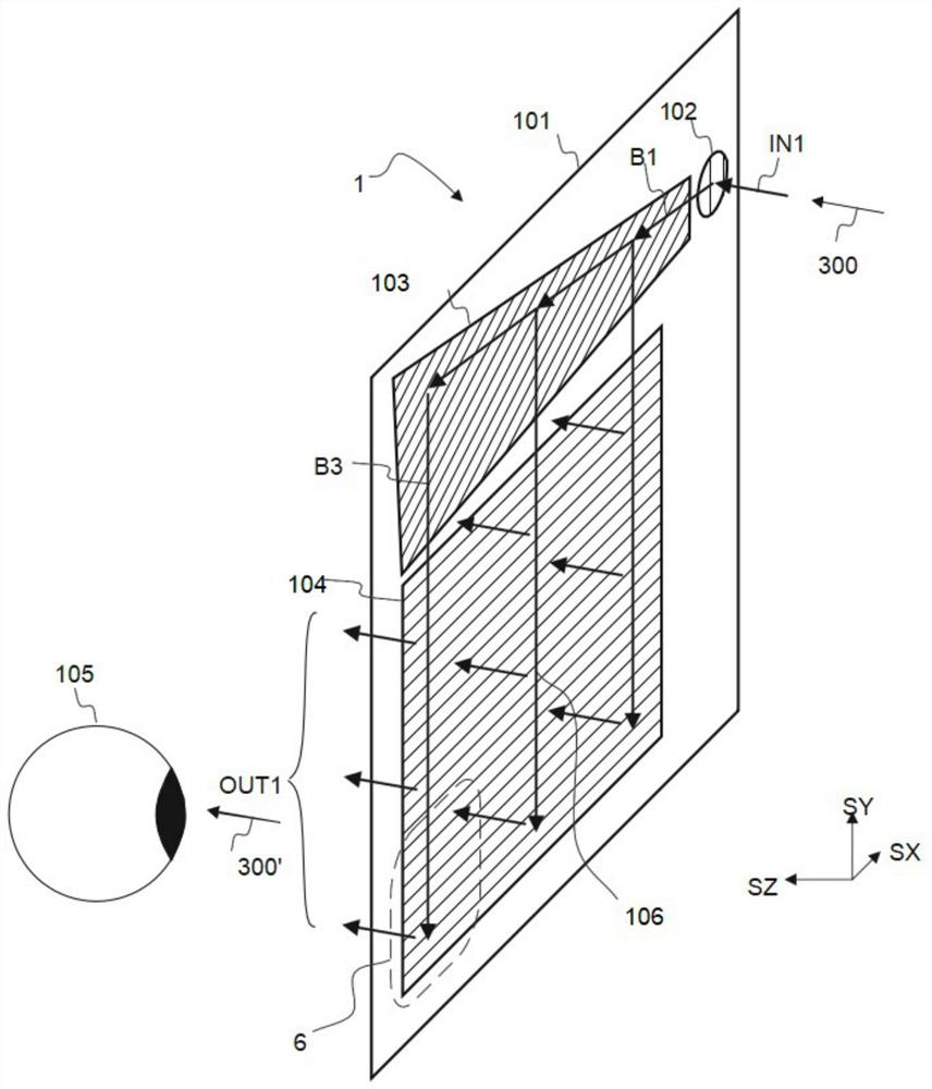
eventually lead to figure 1 The spatial intensity distribution of the output light of the pupil dilating device 1 may be non-uniform

Method used


Image

  • Optical device, display device and method for outputting light and displaying image of display device
  • Optical device, display device and method for outputting light and displaying image of display device
  • Optical device, display device and method for outputting light and displaying image of display device

Examples


Embodiment Construction

[0032] The specific embodiments of the present invention will be further described below in conjunction with the accompanying drawings. It should be noted here that the descriptions of these embodiments are used to help understand the present invention, but are not intended to limit the present invention. In addition, the technical features involved in the embodiments of the present invention described below may be combined with each other as long as they do not conflict with each other.

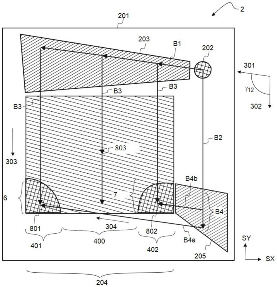
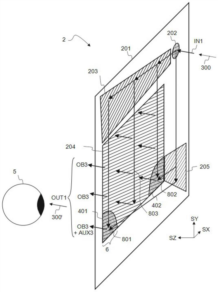
[0033] The optical device of the present application, that is, the pupil expansion device 2, can include a planar waveguide plate 201 with good flatness, which in turn includes a first optical diffraction entrance pupil unit 202, a second optical diffraction pupil expansion unit 203, and a third optical diffraction exit pupil unit 204 and a fourth optical diffraction bypass unit 205 .

[0034] The entrance pupil unit 202 can receive the input beam IN1, and the exit pupil unit 204 can provid...


PUM


Abstract

The invention relates to the technical field of optical devices, in particular to an optical device, a display device and a method for outputting light and displaying an image of the display device. The optical device comprises a waveguide plate and a bypass unit. The waveguide plate includes a diffraction entrance pupil unit for forming first guide light and second guide light by diffracting theinput light, a diffraction pupil expansion unit for diffracting the first guide light to form third guide light, and a diffraction exit pupil unit for diffracting the third guide light to form first output light. The bypass unit that diffracts the second guide light to form fourth guide light; the first guide light is propagated along a first direction, the second guide light is propagated along asecond direction, and an included angle between the first direction and the second direction is in a range of 60-120 degrees; the diffracted exit pupil unit includes one or more enhancement regions to form auxiliary output light by diffracting the fourth guide light. The device provided by the invention can well improve the intensity distribution uniformity of output light.

Description

technical field [0001] The invention relates to the technical field of optical devices, in particular to an optical device, a display device and a method for outputting light and displaying images. Background technique [0002] refer to figure 1 , the pupil expansion device 1 includes a waveguide plate 101 , and the waveguide plate further includes a diffractive entrance pupil unit 102 , a diffractive pupil expanding unit 103 and a diffractive exit pupil unit 104 . An input beam IN1 is expanded through multiple diffractions in the pupil expanding device 1, and finally outputs the beam OUT1. The coupling-in pupil unit 102 diffracts the input light IN1 into the first transmitted light B1 through diffraction. The first guided light B1 is diffracted by the pupil expanding unit 103 to form expanded guided light B3. The diffused guide light B3 is diffracted by the diffractive exit pupil unit 104 and output as light OUT1 . [0003] The pupil expander 1 can expand the beam in bo...

Claims


Application Information

Patent Timeline
Patent Type & Authority Applications(China)
IPC IPC(8): G02B27/01G02B6/124
CPCG02B27/0172G02B6/124G09F13/00G02B2027/0174G02B27/0081F21V7/0091G02B6/0011G02B6/3522
Inventor 塔帕尼·卡列沃·利沃拉蒋厚强朱以胜
Owner SHENZHEN OPTIARK SEMICON TECH LTD
Learn More