Diffraction experiment device and experiment method thereof

An experimental device and a fixed track technology, applied in the field of experimental instruments, can solve the problems of inconvenient use of diffraction experimental instruments and single experimental conditions, and achieve the effects of improving experimental adaptability, simple operation and convenient application.

Active Publication Date: 2020-10-13
马鞍山学院
View PDF25 Cites 1 Cited by
  • Summary
  • Abstract
  • Description
  • Claims
  • Application Information

AI Technical Summary

Problems solved by technology

[0006] The purpose of the present invention is to overcome the inconvenient use of the diffraction experiment instrument in the prior art and the shortcomings of single experimental conditions. It is intended to provide a diffraction experiment device and its experimental method. Using the experimental device of the present invention to conduct experiments can overcome the experimental distance and experimental conditions. The missing defect, and the experimental process is easy to use

Method used


Image

  • Diffraction experiment device and experiment method thereof
  • Diffraction experiment device and experiment method thereof
  • Diffraction experiment device and experiment method thereof

Examples


Embodiment 1

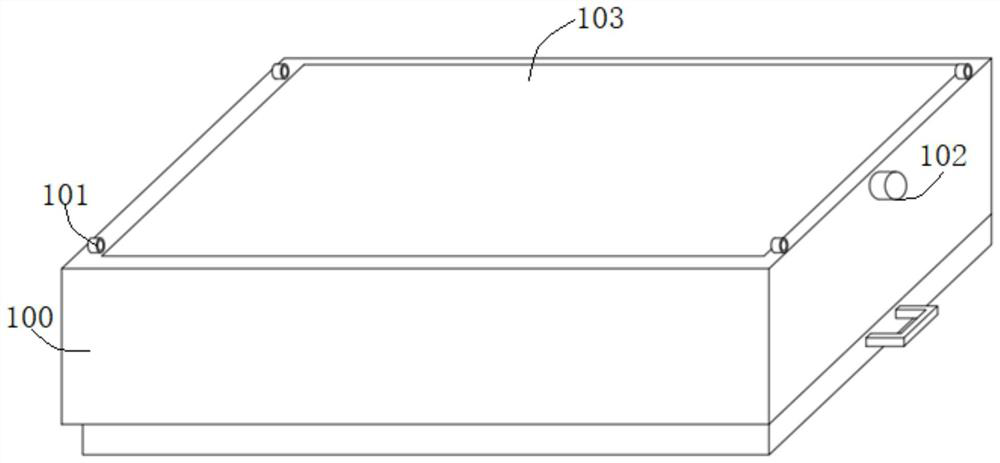
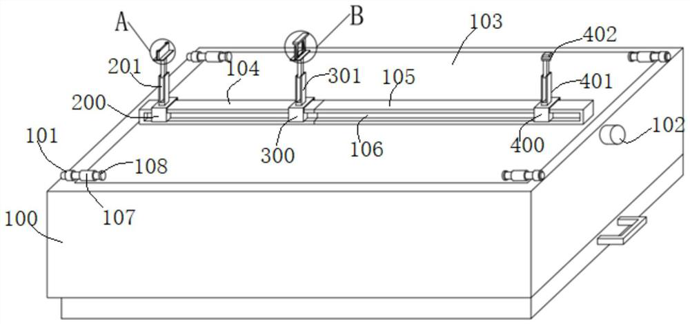
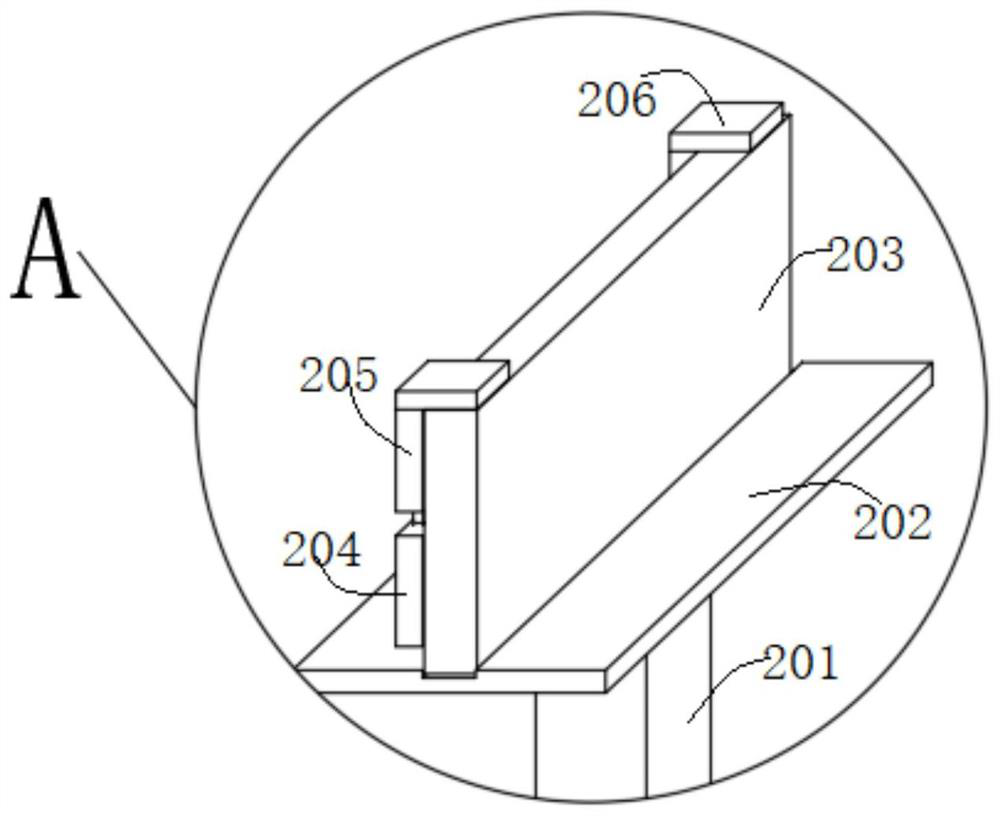
[0037] Such as Figure 1-Figure 5 As shown, a diffraction experiment device of this embodiment includes a fixed rail 104 and a movable rail 105 that are telescopically fitted and connected, and a light source assembly and a baffle that are slidably matched to the rail are sequentially arranged on the fixed rail 104 and the movable rail 105 Components and light screen components; wherein the baffle plate assembly includes a bottom plate 2 302, the two sides of the bottom plate 302 are respectively slidingly fitted with a baffle plate 1 303, and the top of the baffle plate 303 on both sides is connected to a top plate 305; between the baffle plate 1 303 on both sides The width of the gap between them can be adjusted, so that the diffraction phenomenon caused by the change of different lateral distances can be observed, which is beneficial to understand and broaden the experimental cognition.

[0038]Specifically, both sides of the fixed track 104 and the movable track 105 are pr...

Embodiment 2

[0043] A kind of diffraction experimental device of this embodiment is basically the same as that of Embodiment 1. Furthermore, the baffle plate assembly also includes a baffle plate 2 304, and through grooves are opened on the opposite walls of the two baffle plate 1 303, and the baffle plate 2 304 Correspondingly embedded in the through groove, and the second baffle 304 on both sides can be relatively far away from or close to, the bottom of the second baffle 304 is flush with the bottom of the first baffle 303, and the height of the top of the second baffle 304 is lower than the top of the first baffle 303 high. Such as Figure 4 As shown, the second baffle plate 304 can move inside and outside the through groove of the first baffle plate 303. The first baffle plate 303 can specifically adopt the shape of a right-angled trapezoid in cross-section, and open a through groove on its inclined surface. Move inside and outside the surface, and the bottom of baffle plate 2 304 is...

Embodiment 3

[0045] A kind of diffraction experimental device of this embodiment is basically the same as the above-mentioned embodiment, and further, the baffle plate assembly also includes a baffle plate three (not shown in the figure), and the baffle plate three is located at the front side or the rear side of the baffle plate one 303, And the width of the third baffle is sufficient to cover the gap between the first 303 on both sides; the third baffle is movable along the height direction of the first 303 baffle. Specifically, the baffle plate 3 can be suspended under the top plate 305 through bolt fastening, that is, the bolts are screwed from the upper part through the top plate 305 and connected with the baffle plate 3 below, and the up and down height of the baffle plate 3 can be adjusted by rotating the bolts , and the top surface of the baffle plate 3 is also connected with a soft shielding curtain, one side of which is connected to the top plate 305, and one side is fixed on the ...


PUM


Abstract

The invention discloses a diffraction experiment device and an experiment method thereof, and belongs to the field of experiment instruments. The diffraction experiment device comprises a fixed trackand a movable track which are connected in a telescopic fit mode, and a light source assembly, a baffle assembly and an optical screen assembly which are in sliding fit with the tracks are sequentially arranged on the fixed track and the movable track. The baffle assembly comprises a second bottom plate, first baffles are arranged on the two sides of the second bottom plate in a sliding fit mode,a top plate is connected to the tops of the first baffles on the two sides, and the width of the gap between the first baffles on the two sides is adjustable. According to the diffraction experiment device and the experiment method thereof, the defects that in the prior art, diffraction experiment instruments are inconvenient to use and single in experiment condition are overcome, the defect thatthe experiment distance and the experiment condition are lost can be overcome when the experiment device is used for an experiment, and the experiment process is convenient to use.

Description

technical field [0001] The invention relates to the technical field of experimental instruments, more specifically, to a diffraction experimental device and an experimental method thereof. Background technique [0002] Single-slit diffraction is divided into Fresnel diffraction (near field) and folded Fraunhofer diffraction (far field), which is characterized by the deflection of light as the shadow area in geometry, and forms between the geometric illumination area and the shadow area. Light and dark distribution (stripes). Single-slit diffraction is a phenomenon in which light waves encounter obstacles during propagation, and light waves will continue to propagate around obstacles. Diffraction is most pronounced when the wavelength is comparable to or larger than the size of the slit, hole or obstacle. Neither the light source nor the light screen is very far from the obstacle, and no lenses are used. At this time, the light is not parallel light, that is, the wave fron...

Claims


Application Information

Patent Timeline
Patent Type & Authority Applications(China)
IPC IPC(8): G09B23/22
CPCG09B23/22
Inventor 曹兴焕
Owner 马鞍山学院
Why Eureka
Try Eureka