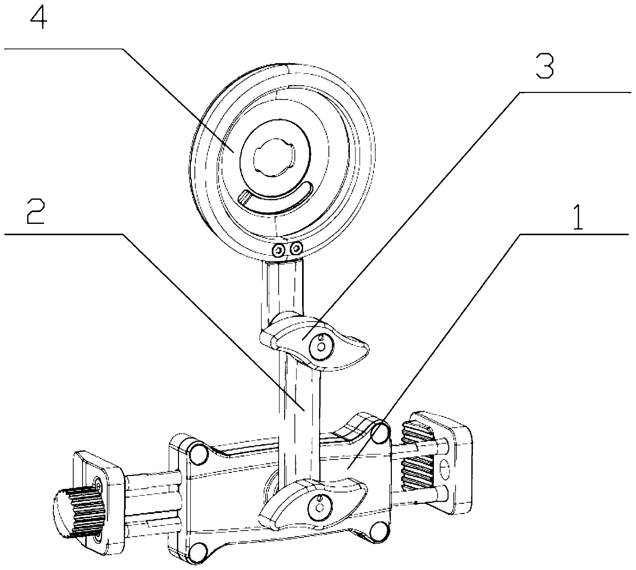
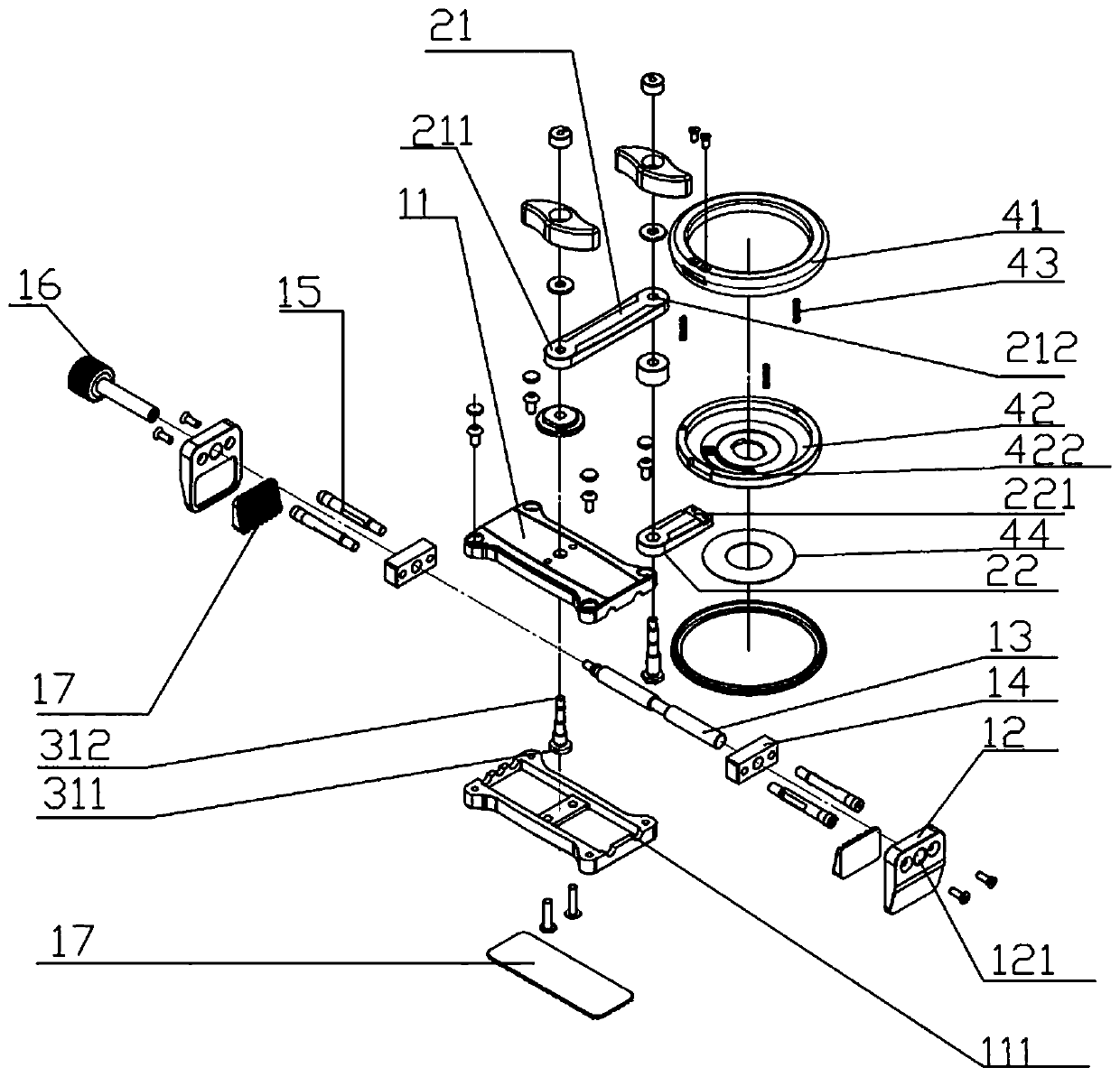
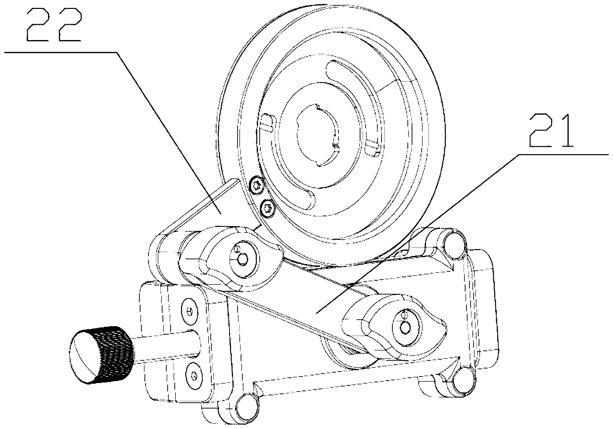
Lens connection device

A connecting device and lens technology, which is applied in the directions of telephone structure, optics, instruments, etc., can solve the problems of inconvenience to carry and the space occupied by the portable connecting and clamping device, and achieve the effect of easy portability or storage and small occupied space.

Pending Publication Date: 2019-06-11
GUANGDONG SIRUI OPTICAL CO LTD
View PDF1 Cites 0 Cited by
  • Summary
  • Abstract
  • Description
  • Claims
  • Application Information

AI Technical Summary

Problems solved by technology

[0005] However, since the overall length of the swing rod is fixed, if the clamping device is to have a larger application range, the swing rod is usually required to be relatively long, which will result in that even if the angle between the swing rod and the fixed plate is adjusted and the swing rod Extending out the length of the fixing plate, the portable connection and clamping device still takes up a lot of space and is inconvenient to carry

Method used


Image

  • Lens connection device
  • Lens connection device
  • Lens connection device

Examples


Embodiment Construction

[0084] The technical solutions of the present invention will be clearly and completely described below in conjunction with the accompanying drawings. Apparently, the described embodiments are some of the embodiments of the present invention, but not all of them. Based on the embodiments of the present invention, all other embodiments obtained by persons of ordinary skill in the art without making creative efforts belong to the protection scope of the present invention.

[0085] In the description of the present invention, it should be noted that the terms "center", "upper", "lower", "left", "right", "vertical", "horizontal", "inner", "outer" etc. The indicated orientation or positional relationship is based on the orientation or positional relationship shown in the drawings, and is only for the convenience of describing the present invention and simplifying the description, rather than indicating or implying that the referred device or element must have a specific orientation, ...


PUM


Abstract

The invention provides a lens connection device, comprising a fixing device which is detachably connected with a device with a camera; a hinge connection rod mechanism, wherein the hinge connection rod mechanism comprises at least two connection rods, the connection rods are equipped with connection parts which are rotationally connected with the fixing device and movable parts which are suitablefor setting an external lens, the movable parts can swing relative to the connection parts, and the movable parts and the connection parts are set on different connection rods; and a locking structurewhich is suitable for locking positions of the movable parts. Through utilization of superposed length of the at least two connection rods, a requirement for a relatively greater distance between theexternal lens and the fixing device is satisfied. A single connection rod does not need to be set too long. The requirement for the relatively greater distance between the external lens and the fixing device can be satisfied, so the lens connection device is applicable to relatively many sizes or models of devices with the cameras, and the lens connection device has a relatively wide applicationrange. The condition that relatively large space is still occupied when the hinge connection rod mechanism is in a retracted state due to overlength of the single connection rod also can be avoided.

Description

technical field [0001] The invention relates to the technical field of display connection equipment, in particular to a lens connection device. Background technique [0002] At present, mobile phones have become an indispensable part of people's daily life. The shooting function of mobile phones has developed rapidly, but there is still a gap compared with professional camera equipment such as digital cameras. The lens can improve the shooting effect and provide the mobile phone with functions such as wide-angle, fisheye, macro, and telephoto to meet people's shooting needs. It is necessary to provide a lens connection device to fix the external lens on the camera of the mobile phone. [0003] Lens connection devices are generally divided into shell-type design and clip-type design. The shell-type design uses a special mobile phone shell as the lens connection device, which can fix the external lens in the housing hole of the corresponding mobile phone camera. The shell-typ...

Claims


Application Information

Patent Timeline
IPC IPC(8): G03B17/12H04M1/02
Inventor 不公告发明人
Owner GUANGDONG SIRUI OPTICAL CO LTD
Why Eureka
Try Eureka