
Rotor assembly and switched reluctance motor

A technology of switched reluctance motors and rotors, applied in magnetic circuit rotating parts, AC motor control, electromechanical devices, etc., can solve the problems of high noise and vibration of switched reluctance motors

Active Publication Date: 2020-10-13
GREE ELECTRIC APPLIANCES INC +1
View PDF4 Cites 0 Cited by
  • Summary
  • Abstract
  • Description
  • Claims
  • Application Information

AI Technical Summary

Problems solved by technology

However, due to the double salient pole structure, the noise and vibration of switched reluctance motors are higher than those of permanent magnet motors and asynchronous motors. Vibration and noise have become the biggest problems limiting the popularization and application of switched reluctance motors. How to reduce noise and vibration has become an issue in recent years. Research Hotspots in the Field of Switched Reluctance Motors

Method used


Image

  • Rotor assembly and switched reluctance motor
  • Rotor assembly and switched reluctance motor
  • Rotor assembly and switched reluctance motor

Examples


Embodiment Construction

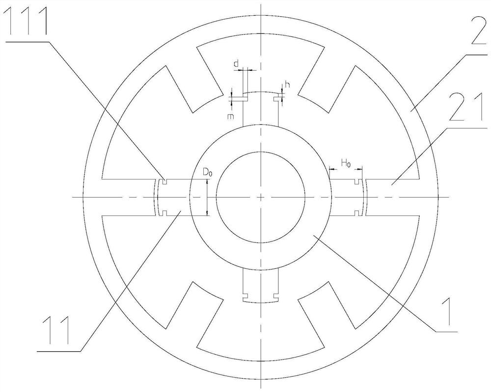
[0027] see in conjunction Figure 1 to Figure 5-2 As shown, according to an embodiment of the present application, a rotor 1 assembly includes:

[0028] The body of the rotor 1 has several rotor teeth 11 on the peripheral wall;

[0029] A groove 111 is provided on a sidewall of at least one of the rotor teeth 11 .

[0030] The present application changes the shape of the rotor tooth 11 by setting a groove 111 on the side wall of the rotor tooth 11, so as to realize the direction of the air gap flux density on the surface of the rotor 1, reduce the radial flux density in the air gap and increase the tangential flux density. Magnetic density, the purpose of suppressing electromagnetic vibration, so it can reduce the vibration and noise of the motor.

[0031] In some embodiments, the groove 111 is provided on a circumferential side wall of the rotor tooth 11 , and the circumferential side wall is a side wall perpendicular to the rotating surface of the rotor tooth 11 .

[0032...


PUM


Abstract

The invention provides a rotor assembly and a switched reluctance motor. The rotor assembly comprises a rotor body, and a plurality of rotor teeth are arranged on the peripheral wall of the rotor body. And a groove is formed in the side wall of at least one rotor tooth. The grooves are formed in the side walls of the rotor teeth to change the direction of the air gap flux density on the surface ofthe rotor, the radial flux density in the air gap can be reduced, meanwhile, the tangential flux density can be increased, and the purpose of restraining electromagnetic vibration is achieved.

Description

technical field [0001] The application belongs to the technical field of switched reluctance motors, and in particular relates to a rotor assembly and a switched reluctance motor. Background technique [0002] The switched reluctance motor has the advantages of simple structure, frequent forward and reverse rotation, small starting current, large starting torque and high efficiency in a wide speed range. Since there are no permanent magnets or windings on the rotor, switched reluctance motors have higher reliability in many harsh environments or occasions. In recent years, they have been widely used in fields such as hybrid vehicles, aerospace and machinery manufacturing. However, due to the double salient pole structure, the noise and vibration of switched reluctance motors are higher than those of permanent magnet motors and asynchronous motors. Vibration and noise have become the biggest problems limiting the popularization and application of switched reluctance motors. H...

Claims


Application Information

Patent Timeline
IPC IPC(8): H02K1/24H02P25/098
CPCH02K1/24H02P25/098H02K2213/03
Inventor 魏正平杨模贵白冰王周叶陈家兴杨静帆
Owner GREE ELECTRIC APPLIANCES INC
Learn More