Handheld stringing device
A rope threader and shaft hole technology, applied in the field of hand tools, can solve problems such as difficulty in realizing rope threading and the like
- Summary
- Abstract
- Description
- Claims
- Application Information
AI Technical Summary
Problems solved by technology
Method used
Image
Examples
Embodiment 1
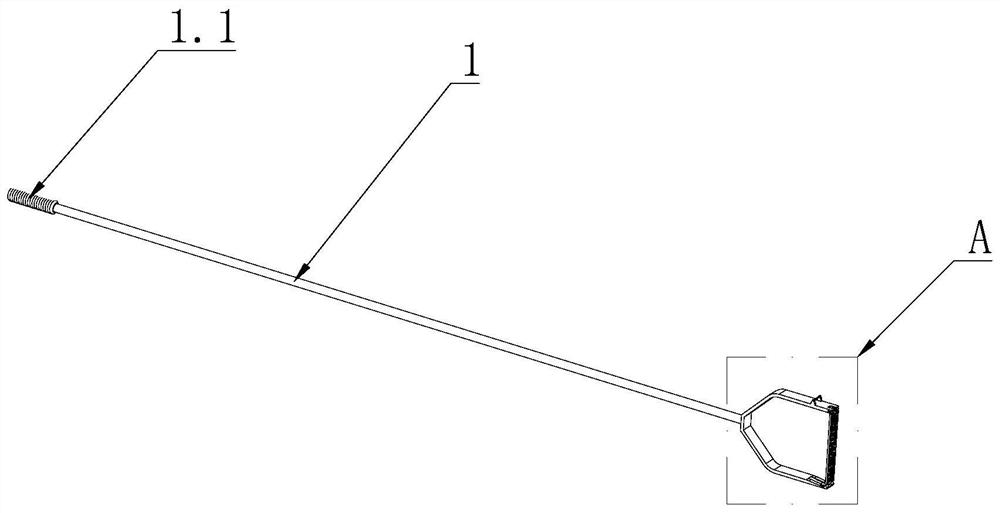
[0052] The invention provides a hand-held rope threader, which includes such as figure 1 As shown in the main rod 1, the front end of the main rod 1 is provided with a C-shaped or U-shaped bearing body 2; the rear end of the main rod 1 is provided with a handshake part 1.1, which is convenient for the operator to grasp; the bearing body The two ends of 2 are facing away from the side of the main rod 1, and the front end of the main rod 1 is connected to the middle position of the bearing body 2, and the bearing body 2 is provided with a rope head that can drive the rope to go around the object and follow the main body. Rope threading mechanism for rod 1 pullback.
[0053] The connection between the front end of the above-mentioned main rod 1 and the bearing body 2 can be detachable connection such as thread or clamping, or can be fixed connection such as welding.
Embodiment 2
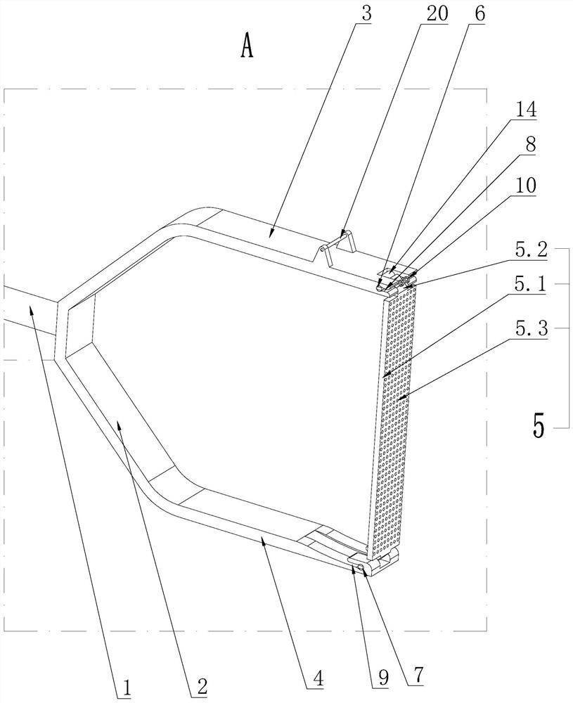
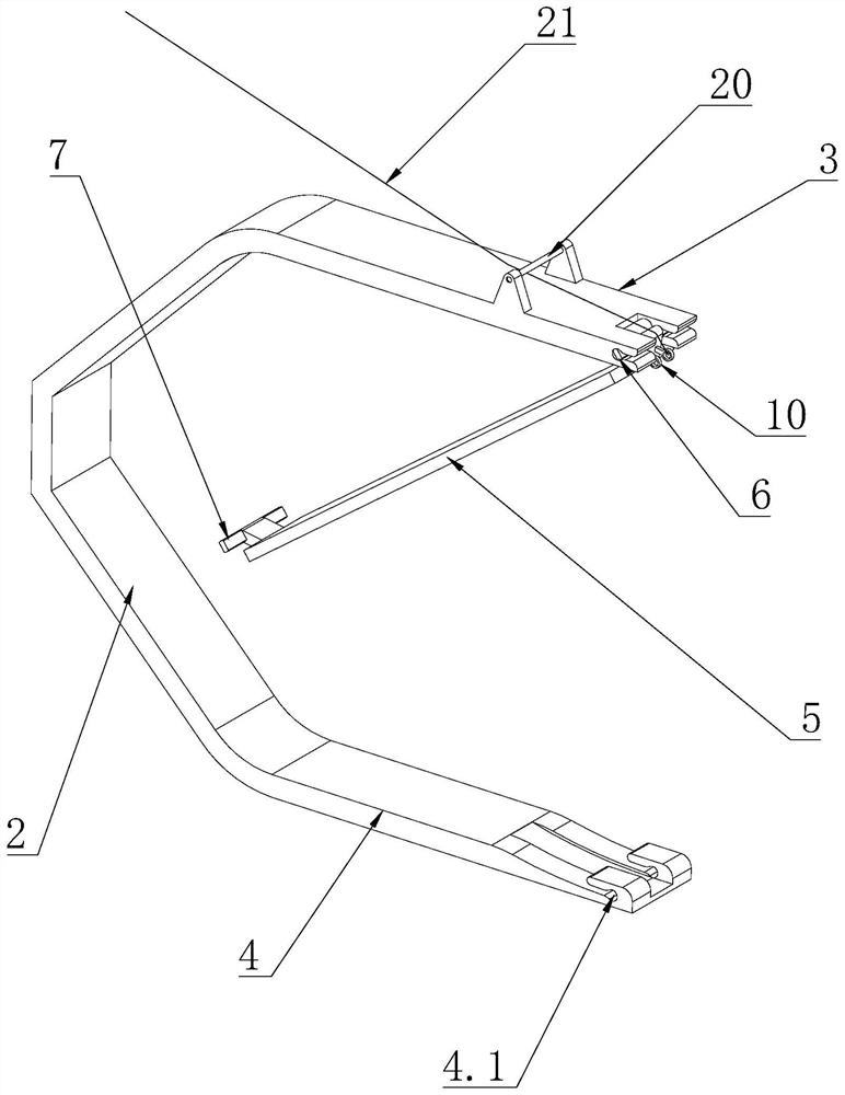
[0055] The basic structure is the same as that of Embodiment 1, the difference is: as figure 2 As shown, the two ends of the carrying body 2 are respectively provided with an upper arm 3 and a lower arm 4, the upper arm 3 and the lower arm 4 are parallel to each other, and the rear end of the upper arm 3 and the rear end of the lower arm 4 are respectively connected to the ends of the carrying body 2 , the rear end of the above-mentioned upper arm 3 and the rear end of the lower arm 4 are respectively connected to the end of the bearing body 2, which may be a detachable connection of a split structure, or an integral structure with the bearing body 2; the upper arm 3 The above-mentioned rope-threading mechanism is provided between the front end of the lower arm 4 and the front end of the lower arm 4, and the rope-threading mechanism includes a movable part 5. The movable part 5 is in a long strip structure, and the upper and lower ends of the movable part 5 alternate Cooperat...
Embodiment 3
[0060] The basic structure is the same as that of the second embodiment, the difference is that: the upper end of the movable part 5 is provided with a buckle 10 for tying the end of the rope 21 . As preferably, the ring buckle 10 such as Figure 18 A circular structure is shown. But the function of this ring buckle 10 is to facilitate the rope end of the rope to be fixed on the upper end of the movable part 5, so as long as it can realize the rope end of the rope 21 to fasten and fix the parts, it should be included in the ring buckle 10 of the present application. within range. For example, the buckle 10 is a semicircular structure, and the buckle 10 is a drum-shaped structure with a small diameter in the middle and a large diameter at both ends. One end of the buckle 10 of the drum-shaped structure is fixedly connected to the upper end of the movable part 5 .
PUM
 Abstract
Description
Claims
Application Information
 - R&D
- Intellectual Property
- Life Sciences
- Materials
- Tech Scout
- Unparalleled Data Quality
- Higher Quality Content
- 60% Fewer Hallucinations
Browse by: Latest US Patents, China's latest patents, Technical Efficacy Thesaurus, Application Domain, Technology Topic, Popular Technical Reports.
© 2025 PatSnap. All rights reserved.Legal|Privacy policy|Modern Slavery Act Transparency Statement|Sitemap|About US| Contact US: help@patsnap.com


