Hand-held stringing device

A rope threader, hand-held technology, applied in the field of hand tools, can solve problems such as difficulty in realizing rope threading

Active Publication Date: 2020-10-16
SUZHOU YAOKAI INFORMATION TECH CO LTD
View PDF18 Cites 1 Cited by
  • Summary
  • Abstract
  • Description
  • Claims
  • Application Information

AI Technical Summary

Problems solved by technology

[0003] However, the existing tethering process often requires personnel to approach the object before it can be manually operated. For objects that cannot be touched by personnel, it is difficult to realize the rope passing through or around the object to complete the process of connecting through the rope.

Method used


Image

  • Hand-held stringing device
  • Hand-held stringing device
  • Hand-held stringing device

Examples


Embodiment 1

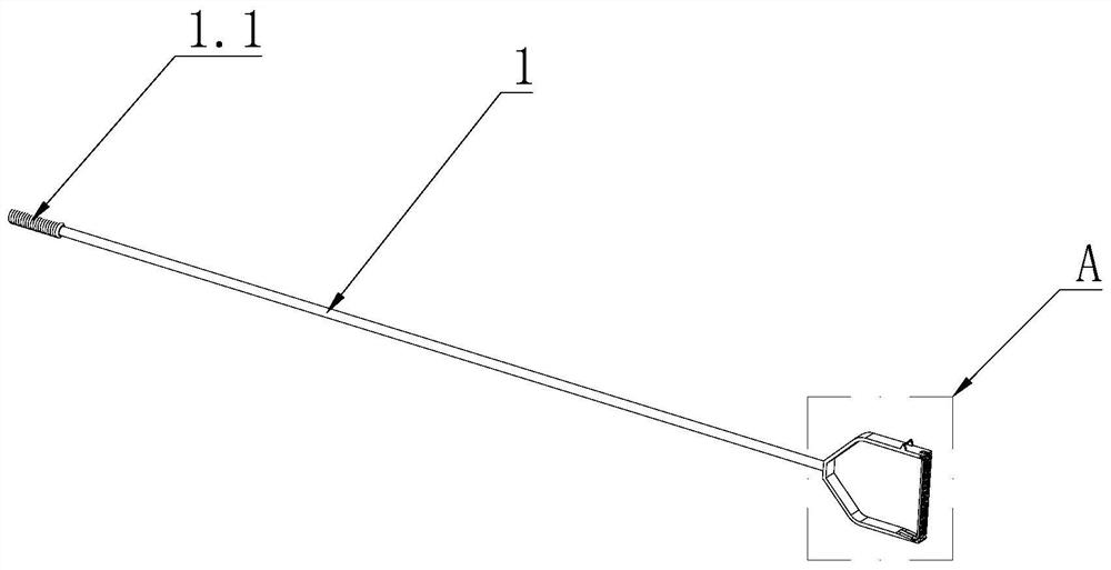
[0054] The invention provides a hand-held rope threader, which includes such as figure 1 As shown in the main rod 1, the front end of the main rod 1 is provided with a C-shaped or U-shaped bearing body 2; the rear end of the main rod 1 is provided with a handshake part 1.1, which is convenient for the operator to grasp; the bearing body The two ends of 2 are facing away from the side of the main rod 1, and the front end of the main rod 1 is connected to the middle position of the bearing body 2, and the bearing body 2 is provided with a rope head that can drive the rope to go around the object and follow the main body. Rope threading mechanism for rod 1 pull back.

[0055] The connection between the front end of the above-mentioned main rod 1 and the bearing body 2 can be detachable connection such as thread or clamping, or can be fixed connection such as welding.

Embodiment 2

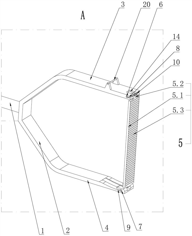
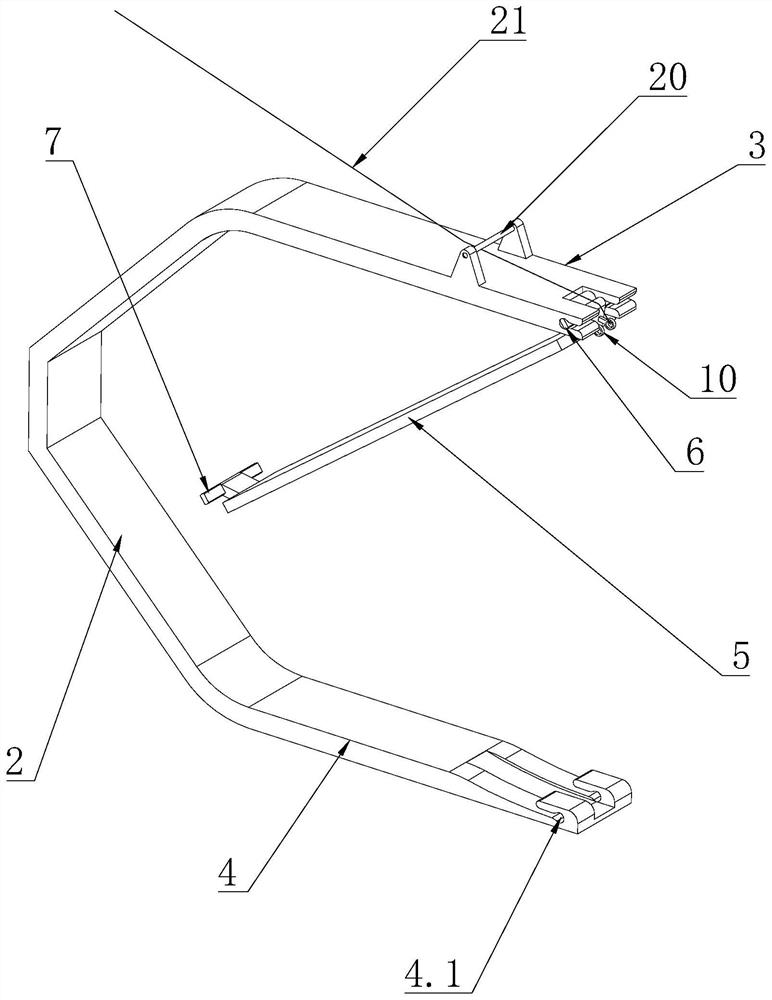
[0057] The basic structure is the same as that of Embodiment 1, the difference is: as figure 2 As shown, the two ends of the carrying body 2 are respectively provided with an upper arm 3 and a lower arm 4, the upper arm 3 and the lower arm 4 are parallel to each other, and the rear end of the upper arm 3 and the rear end of the lower arm 4 are respectively connected to the ends of the carrying body 2 , the rear end of the above-mentioned upper arm 3 and the rear end of the lower arm 4 are respectively connected to the end of the bearing body 2, which may be a detachable connection of a split structure, or an integral structure with the bearing body 2; the upper arm 3 The above-mentioned rope-threading mechanism is provided between the front end of the lower arm 4 and the front end of the lower arm 4, and the rope-threading mechanism includes a movable part 5. The movable part 5 is in a long strip structure, and the upper and lower ends of the movable part 5 alternate Cooperat...

Embodiment 3

[0062] The basic structure is the same as that of the second embodiment, the difference is that: the upper end of the movable part 5 is provided with a buckle 10 for tying the end of the rope 21 . As preferably, the ring buckle 10 such as Figure 18 A circular structure is shown. But the function of this ring buckle 10 is to facilitate the rope end of the rope to be fixed on the upper end of the movable part 5, so as long as it can realize the rope end of the rope 21 to fasten and fix the parts, it should be included in the ring buckle 10 of the present application. within range. For example, the buckle 10 is a semicircular structure, and the buckle 10 is a drum-shaped structure with a small diameter in the middle and a large diameter at both ends. One end of the buckle 10 of the drum-shaped structure is fixedly connected to the upper end of the movable part 5 .


PUM


Abstract

The invention discloses a stringing device. The device includes a main rod, a bearing body is arranged at one end of the main rod, an upper arm and a lower arm are arranged on the bearing body, and amoving part is arranged between the upper arm and the lower arm. The device is characterized in that the moving part includes an expansion rod, bending parts inclining toward the bearing body are arranged at two ends of the expansion rods, an upper rotating shaft and a lower rotating shaft are arranged on the bending parts respectively, upper shaft holes matched with the upper rotating shaft are arranged on the upper arm, a first channel is arranged on the upper arm, lower shaft holes matched with the lower rotating shaft are arranged on the lower arm, a second channel is arranged on the lowerarm, and a ring buckle is arranged at the upper end of the moving part. The hand-held stringing device can enable people to make a rope penetrate through holes in objects or bypass the objects and towithdraw a rope head of the rope finally under the statement that people are far away from the objects.

Description

technical field [0001] The invention relates to the technical field of hand tools, in particular to a hand-held rope threader. Background technique [0002] Passing a rope through a hole in an object and then looping it back from the outside of the object or around a rod-shaped object and then retracting the rope is a common way of connecting objects with a rope, which has been applied in various industries, such as when a ship is docked The crew needs to pass the rope through the iron ring on the pier and then go back to the ship to tie the rope; or when the buoy is being repaired, it is necessary to pass the rope on the ship through the fixed ring above the buoy and then go back to the ship to complete the pulling of the buoy; or in the field of construction Middle construction workers need to pass the safety rope through the safety ring at the height of the wall or on the top steel frame to realize the installation of the safety rope. [0003] However, the existing tethe...

Claims


Application Information

Patent Timeline
Patent Type & Authority Applications(China)
IPC IPC(8): B65H51/00
CPCB65H51/00
Inventor 李先建
Owner SUZHOU YAOKAI INFORMATION TECH CO LTD
Why Eureka
Try Eureka