
Power equipment detection equipment

A technology for testing equipment and power equipment, which is applied to the parts of electrical measuring instruments, measuring equipment, and measuring devices. It can solve problems such as difficult to distinguish wire parts, wires are entangled with each other, and affect the detection value of electrical equipment.

Inactive Publication Date: 2020-10-23
广州沐风信息科技有限公司
View PDF0 Cites 3 Cited by
  • Summary
  • Abstract
  • Description
  • Claims
  • Application Information

AI Technical Summary

Problems solved by technology

[0004] For the existing electric equipment testing equipment, in order to meet the multi-faceted detection of electric equipment, there is a plug-in interface. However, it is often necessary to use multiple plug-in interfaces at the same time during detection, so that multiple wires are required Connection, the cut wires are of different lengths, if they are too long, they will be hung between the detection equipment and the power equipment, and the wires are prone to intertwining, making it difficult to distinguish the corresponding parts of the wires, thus affecting the detection value of the power equipment. , the present invention provides a power equipment testing equipment to solve the above technical problems

Method used


Image

  • Power equipment detection equipment
  • Power equipment detection equipment
  • Power equipment detection equipment

Examples


Embodiment 1

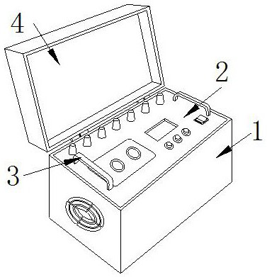
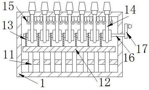
[0029] The present invention provides a testing device for electrical equipment, the structure of which includes a portable case 1, a detection panel 2, a handle 3, and an upper cover 4, the detection panel 2 is embedded in the portable case 1, and the bottom of the handle 3 is welded to the detection panel 2 upper surface, the upper cover 4 is connected to one side of the portable case 1 through a hinge, and the portable case 1 includes a support rod 11, a data processing board 12, a connecting rod 13, a positioning rod 14, a guide roller 15, a rotating rod 16, Rotating handle 17, the support rod 11 is welded on the bottom of the portable case 1, the data processing board 12 is connected to the end of the support rod 11 by bolts, the bottom of the connecting rod 13 is embedded in the top of the data processing board 12, the positioning The left side of the bottom of the rod 14 is installed on the right side of the connecting rod 13, and the top runs through the upper wall of t...

Embodiment 2

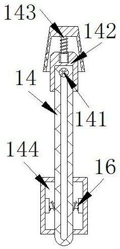
[0035] In the figure, the positioning rod 14 includes a wire insertion interface 141, a top block 142, a turning block 143, and a wire receiving cavity 144. At the top of the rod 14, the turning block 143 is engaged with the top block 142, and the take-up cavity 144 is installed at the bottom of the positioning rod 14 and is engaged with the rotating rod 16. There is a screw groove on the upper surface of the top block 142, and the turning block The inside of 143 is provided with a screw rod to engage with the screw groove, and the surface of the rotary block 143 is uneven, which is beneficial to rotating the rotary block 143 to connect the wires to the inside of the plug-in interface 141, so as to avoid that the wires fall off during the detection and affect the detection results of the electric equipment.

[0036] In the figure, the wire receiving cavity 144 is composed of a fixed block b1, a rotating shaft b2, a runner b3, a support cylinder b4, a limit plate b5, and a torsi...


PUM


Abstract

The invention discloses power equipment detection equipment. The equipment structurally comprises a portable box, a detection panel, a handle and an upper cover, wherein the detection panel is fixedlyembedded in the portable box, the bottom of the handle is welded on an upper surface of the detection panel, and the upper cover is connected with one side of the portable box through a hinge. The equipment is advantaged in that when the power equipment is detected, a rotating block is rotated to insert one end of a lead into a plug wire interface and penetrate through a stay wire rod, a rubber block pushes a clamping plate to clamp the wire, the other end of the wire is connected with power equipment, the rotating handle is rotated to enable the rotating rod to drive a take-up cavity to rotate to enable the stay wire rod to move downwards, therefore, the overlong wire is collected into a wire collecting cavity, that parts corresponding to the wires are difficult to distinguish due to winding of the wires is avoided, a torsion spring enables a rotating shaft to have rotating force for rotation, so the wire can be rapidly pulled into the take-up cavity and wound on the outer side of alimiting plate, an elastic ball and a fixing rod support the limiting plate, and disordered wire storage caused by deformation of the limiting plate is avoided.

Description

technical field [0001] The invention relates to the field of electric equipment, in particular to an electric equipment detection equipment. Background technique [0002] Power detection equipment refers to the equipment for testing and testing the power generation equipment and power supply equipment, which can detect the failure of power equipment in time, provide a guarantee for the safety and reliability of power operation, and avoid accidents when using power equipment. Security risks. [0003] At present, there is a kind of power equipment testing equipment that is equipped with a plug-in interface in order to meet the multi-faceted testing of power equipment. For connection, the cut wires are of different lengths, and if they are too long, they will hang between the testing equipment and the power equipment, and the wires are prone to intertwining, making it difficult to distinguish the corresponding parts of the wires, thus affecting the detection value of the power...

Claims


Application Information

Patent Timeline
Patent Type & Authority Applications(China)
IPC IPC(8): G01R31/00G01R1/02G01R1/04B65H75/02
CPCB65H75/02G01R1/02G01R1/04G01R31/00
Inventor 杨玉华
Owner 广州沐风信息科技有限公司
Learn More