High-voltage switch cabinet

A high-voltage switchgear and pressure relief technology, applied in the field of switchgear, can solve the problems of difficult to fully guarantee safety performance and many triggering conditions.

Active Publication Date: 2020-10-23
浙江天润电气有限公司
View PDF11 Cites 1 Cited by
  • Summary
  • Abstract
  • Description
  • Claims
  • Application Information

AI Technical Summary

Problems solved by technology

[0003] In the prior art, the pressure relief method of the switchgear needs to generate high-pressure gas in the switchgear and at the same time, the generated gas must reach a certain pressu

Method used


Image

  • High-voltage switch cabinet
  • High-voltage switch cabinet
  • High-voltage switch cabinet

Examples


Embodiment 1

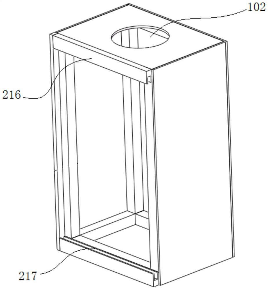
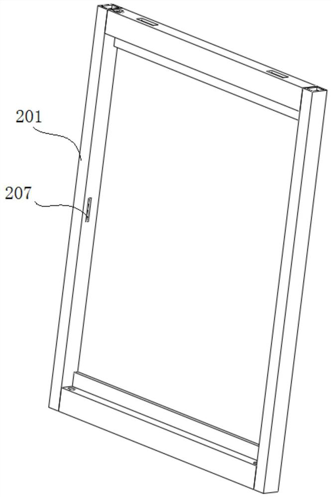
[0032] A high voltage switchgear, such as Figure 1-Figure 6 As shown, the cabinet body is provided with a cabinet door. The cabinet door includes a door frame 201. The door frame 201 is a cuboid frame structure including an upper end bar, a lower end bar, a left end bar and a right end bar. The upper end bar of the frame of the door frame 201 and The lower end rods are respectively provided with limiting plates extending towards the frame to limit the door body 202. When the door body 202 is fastened in the door frame 201, the upper and lower ends of the rear end surface of the door body 202 are respectively against the upper and lower limit positions. on the board to prevent the door body 202 from being pushed into the inside of the switch cabinet.

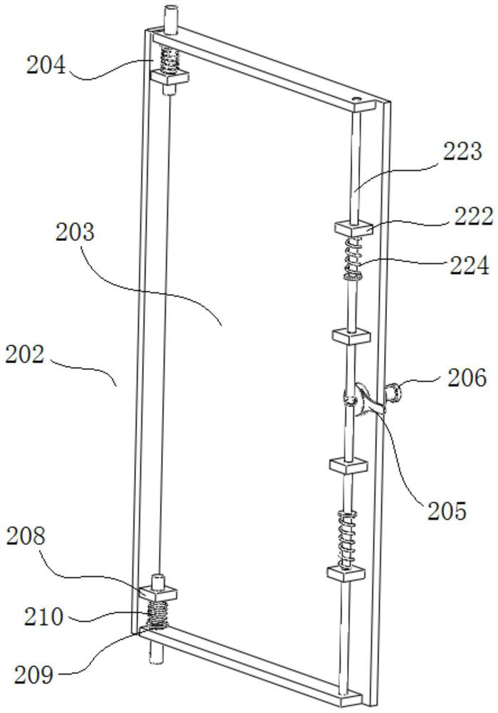
[0033] Door body 202 is hinged in door frame 201, and door body 202 comprises door panel 203, also comprises the upper end plate and the lower end plate that are respectively arranged on the upper and lower ends of door panel 20...


PUM


Abstract

The invention relates to a switch cabinet. The invention discloses a high-voltage switch cabinet. The switch cabinet comprises a pressure relief mechanism, the pressure relief mechanism comprises a pressure relief base fixed on the inner surface of the upper top plate; the pressure relief base comprises a cylindrical pressure relief base side wall with the upper end and the lower end open and a pressure relief mounting base located at the lower end of the pressure relief base side wall and located in the pressure relief base side wall. The pressure relief mounting base is connected with the inner surface of the pressure relief base side wall through a plurality of connecting rods evenly arranged around the axis of the pressure relief base side wall. A pressure relief plate is installed atthe upper end of the side wall of the pressure relief base, a pressure relief channel is formed in the middle of the pressure relief plate, a pressure relief plug is arranged in the pressure relief channel, an electromagnet capable of attracting the pressure relief plate is installed on the upper end face of the side wall of the pressure relief base, and a longitudinally-arranged compression spring is installed between the lower surface of the pressure relief plate and the pressure relief installation base. The pressure relief mechanism is arranged on the switch cabinet, pressure relief can beconducted on gas with different pressures, triggering is sensitive, and safety can be effectively guaranteed.

Description

technical field [0001] The invention relates to a switch cabinet, in particular to a high-voltage switch cabinet. Background technique [0002] A short-circuit fault in the switchgear may generate a short-circuit current of tens of thousands of amperes. The short-circuit current will generate high-temperature and high-pressure gas in an instant. If the faulty air flow cannot be effectively released in a short time, it will easily cause the switchgear to burst. Therefore Switchgear pressure relief is an item that must be considered in the design of switchgear. [0003] In the prior art, the pressure relief method of the switchgear needs to generate high-pressure gas in the switchgear and at the same time, the generated gas must reach a certain pressure to ensure that the pressure relief plate is opened for pressure relief. The pressure relief method requires many trigger conditions. Safety performance is difficult to be fully guaranteed. Contents of the invention [0004]...

Claims


Application Information

Patent Timeline
IPC IPC(8): H02B1/30H02B1/38E05D7/081E05C9/04
CPCH02B1/30H02B1/306H02B1/38E05D7/081E05C9/043
Inventor 童克安格
Owner 浙江天润电气有限公司
Why Eureka
Try Eureka