Sliding type anti-pinch escalator

An anti-pinch escalator and sliding technology, which is applied in escalators, transportation and packaging, etc., can solve the problems of foreign matter entering the apron and steps, trigger insensitivity, safety accidents, etc., to avoid injury, reset easily, and trigger sensitively Effect

Pending Publication Date: 2021-11-19
HANGZHOU XO ELEVATOR
View PDF6 Cites 0 Cited by
  • Summary
  • Abstract
  • Description
  • Claims
  • Application Information

AI Technical Summary

Problems solved by technology

There is a certain gap between the skirt board and the steps of the escalator. When the escalator is working normally, foreign matter may enter the gap between the skirt board and the steps, resulting in a dangerous situation.
Most of the current escalator anti-pinch devices use the deformation of the apron plate installed between the steps to trigger the safety switch, and the national standard has strict requirements on the deformation of the apron plate after being stressed. Therefore, there is a problem of insensitive triggering, which is likely to cause safety problems ACCIDENT

Method used


Image

  • Sliding type anti-pinch escalator
  • Sliding type anti-pinch escalator
  • Sliding type anti-pinch escalator

Examples


Embodiment 1

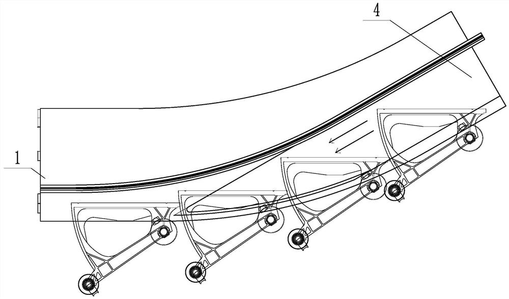
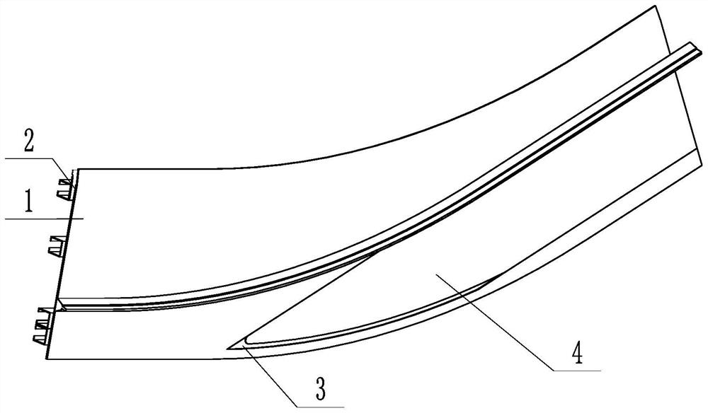
[0035] A sliding anti-pinch escalator, such as Figures 1 to 3 As shown, the apron plate of the escalator includes an apron outer plate 1 close to the steps and an apron support plate 2 away from the steps. The apron outer plate 1 is provided with a sliding notch 3, and the sliding notch 3 is provided with an anti-splitting plate 4, and the apron The support plate 2 is provided with a guide groove 5 corresponding to the anti-splitting plate 4 , and the anti-splitting plate 4 is slidably connected to the apron support plate 2 through the guide groove 5 .

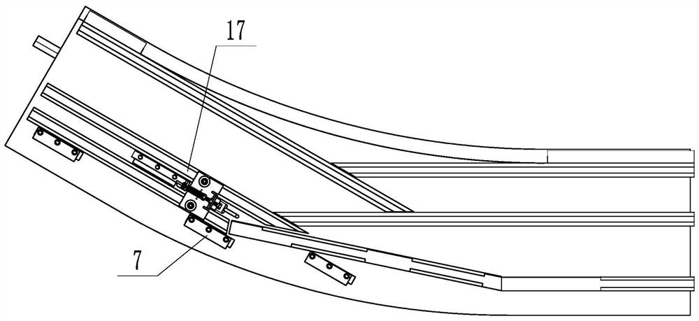
[0036] Such as Figure 4As shown, the side of the anti-splitting plate 4 close to the apron support plate 2 is fixedly connected with several clips 7, the clips 7 extend into the guide groove 5, and the clips 7 protrude toward the apron support plate 2. There is a gap between the apron support plate 2. The structure realizes how the anti-clamping plate 4 is slidably connected to the apron support plate 2 . After it is put ...

Embodiment 2

[0040] The difference technical feature of present embodiment and embodiment 1 is:

[0041] Such as Figure 8 , 9 As shown, the side of the apron support plate 2 facing the anti-splitting plate 4 and the side of the anti-splitting plate 4 facing the apron support plate 2 are all provided with corresponding air flow channels 19, and the air flow channels 19 match to form air holes 20, and the apron support plate 2 also has A blower is provided, and the blower ventilates in the air hole 20, and the end of the air flow channel 19 is provided with a blocking block 21. When the anti-splitting plate 4 slides, the blocking block 21 on the anti-splitting plate 4 and the apron support plate 2 merges to block the air hole 20 , the airflow blown by the blower passes between the anti-splitting plate 4 and the apron support plate 2 and reduces the friction between the two plates.

[0042] The structure plays a role of reducing friction. When foreign matter invades, an external force is ...


PUM


Abstract

The invention discloses a sliding type anti-pinch escalator and aims to overcome the defects that an existing escalator anti-pinch trigger structure is an irreversible trigger structure, is limited by the strength requirement of an escalator and is slow to trigger. The sliding type anti-pinch escalator comprises an apron outer plate close to a step and an apron supporting plate far away from the step, wherein a sliding notch is formed in the apron outer plate; an anti-pinch plate is arranged on the sliding notch; a guide groove corresponding to the anti-pinch plate is formed in the apron supporting plate; the anti-pinch plate is slidably connected onto the apron supporting plate through the guide groove; and the anti-pinch plate is elastically connected with a safety switch. Compared with traditional deformation triggering, the triggering force of the anti-pinch plate at each position is the same, so that the triggering area is enlarged, the triggering is more sensitive, the personal injury is reduced, the anti-pinch plate is simple to reset after being triggered, the damage to the escalator is avoided, and the restarting work of the escalator can be quickly recovered.

Description

technical field [0001] The present invention relates to an escalator protective device, more specifically, it relates to a sliding type anti-pinch escalator. Background technique [0002] Escalators save the consumption of people moving between floors and improve people's lives. With the increasing application of escalators, people pay more and more attention to safety. There is a certain gap between the skirt board and the steps of the escalator. When the escalator is working normally, foreign objects may enter the gap between the skirt board and the steps, resulting in dangerous situations. Most of the current escalator anti-pinch devices use the deformation of the apron plate installed between the steps to trigger the safety switch, and the national standard has strict requirements on the deformation of the apron plate after being stressed. Therefore, there is a problem of insensitive triggering, which is likely to cause safety problems ACCIDENT. [0003] Therefore, th...

Claims


Application Information

Patent Timeline
Patent Type & Authority Applications(China)
IPC IPC(8): B66B29/04
CPCB66B29/04
Inventor 周俊良马凯标邵卫锋张增强吴大将
Owner HANGZHOU XO ELEVATOR
Why Eureka
Try Eureka