Light guide plates and backlight module

a technology of guide plates and backlight modules, which is applied in the direction of instruments, lighting and heating apparatuses, optical elements, etc., can solve the problem of reducing the uniformity of illumination of direct-type backlight modules b>10/b>

Active Publication Date: 2011-12-06
TSINGHUA UNIV +1
View PDF10 Cites 29 Cited by
  • Summary
  • Abstract
  • Description
  • Claims
  • Application Information

AI Technical Summary

Benefits of technology

[0005]Referring to FIG. 4, a direct-type backlight module 10, according to the prior art, is shown. The direct-type backlight module 10 includes a plurality of point light sources 11, a reflective plate 12, a light guide plate 13 and several layers of optical film (not labeled). The reflective plate 12 contains a plurality of through holes 120. Each through hole 120 corresponds to a point light source 11 and each point light source 11 extends through the corresponding through hole 120 to completely illuminate the light guide plate 13. A random number of scattering dots 130 are radially allocated on a surface of the light guide plate 13 with a central point opposite to the reflective plate 12. However, the light guide plate 13 usually is in square or rectangular form. Therefore, the light output from the light guide plate 13 is not uniform, thereby reducing the uniformity of illumination of the direct-type backlight module 10.

Problems solved by technology

However, liquid crystal displays are not self-luminescent, therefore, backlight modules are typically required.
Therefore, the light output from the light guide plate 13 is not uniform, thereby reducing the uniformity of illumination of the direct-type backlight module 10.

Method used


Image

  • Light guide plates and backlight module
  • Light guide plates and backlight module
  • Light guide plates and backlight module

Examples


first embodiment

[0023]In a first embodiment, a1=0.1, a2=6, a3=8, and the number of the scattering dots 220 on each circle are shown in the following table 1.

[0024]

TABLE 1r (mm)45678910111213141516e00000004812162432r (mm)171819202122232425262728e364856647688100112128144156176

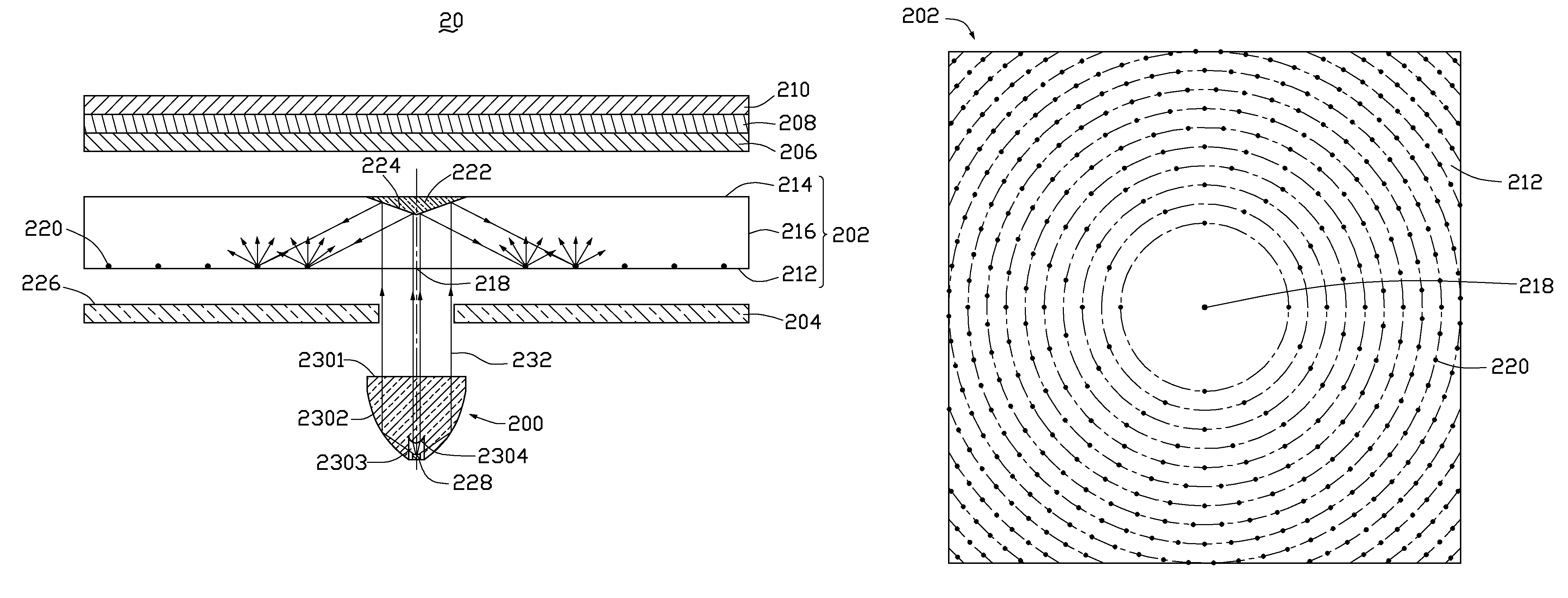
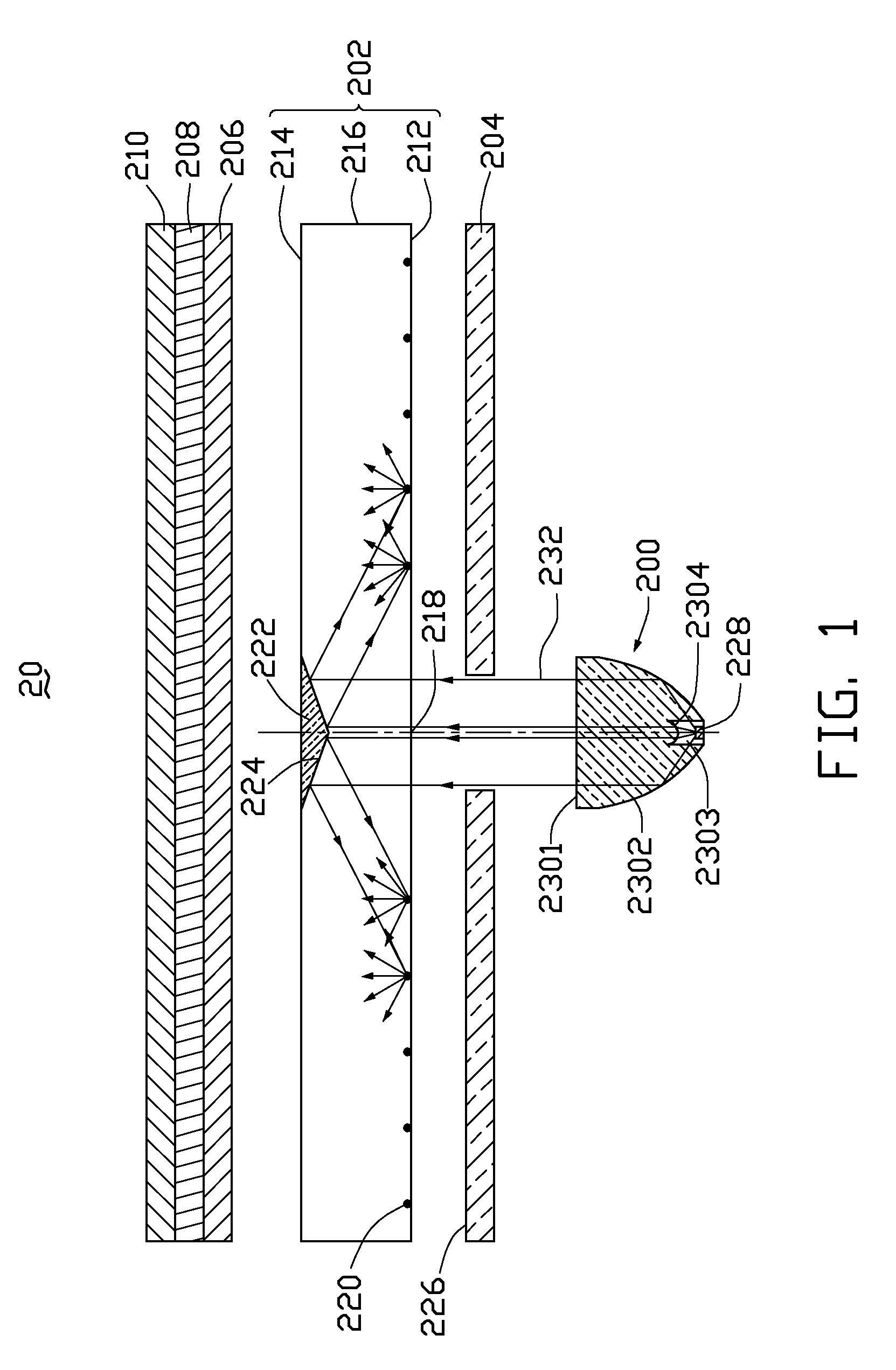
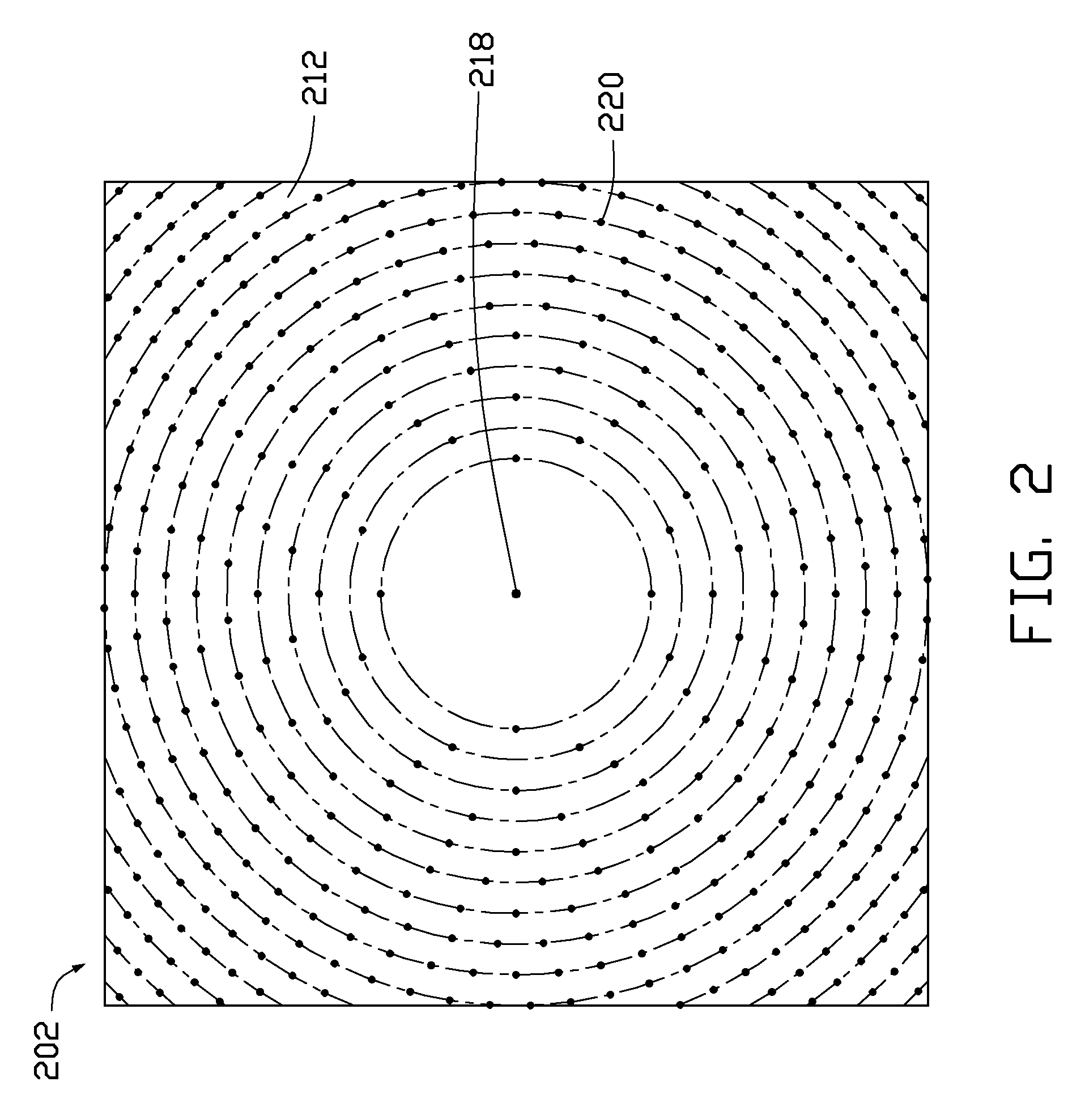
[0025]As shown in table 1, when r≦10 millimeters, there is no scattering dots 220 on the area of the bottom surface 212 because the light radiated from the light source 200 is reflected by the reflector 222 and enters the light guide plate 202 to illuminate the area of the bottom surface 212 with r≦10 millimeters. When 11≦r≦20 millimeters, the scattering dots 220 on the bottom surface 212 are arranged in the form of concentric circles around the center 218 and a distance between the adjacent two circles is equal to 1 millimeter. When r≧21 millimeters, the scattering dots 220 are arranged in the form of concentric arcs on the four corners of the bottom surface 212 because the shape of the guide plate 202 is square and a distance ...

second embodiment

[0026]In a second embodiment, a1=0.1, a2=6, a3=12, and the number of the scattering dots 220 on each circle are shown in the following table 2.

[0027]

TABLE 2r (mm)45678910111213141516e40000000004816r (mm)171819202122232425262728e202836445264728496112124140

third embodiment

[0028]In a third embodiment, a1=0.08, a2=10, a3=10, and the number of the scattering dots 220 on each circle are shown in the following table 3.

[0029]

TABLE 3r (mm)45678910111213141516e8840000000488r (mm)171819202122232425262728e1220243236445260728092100


PUM


Abstract

A light guide plate includes a body having a bottom surface and a light output surface opposite to the bottom surface. A reflector is located on the light output surface opposite to the center of the bottom surface. The reflector is a cavity concaved from the light output surface to the inside of the body. A plurality of scattering dots are located on the bottom surface. The scattering dots are arranged in the form of a plurality of concentric circles around the center of the bottom surface. The number of the scattering dots is defined based on a radius of the circle they reside on, and the radius of the circle is greater than or substantially equal to 4 millimeter.

Description

BACKGROUND[0001]1. Technical Field[0002]The present disclosure relates to light guide plates and backlight modules and, particularly, to a light guide plate for direct-type backlight module and a direct-type backlight module.[0003]2. Description of Related Art[0004]Currently, because liquid crystal displays (LCDs) are thin, lightweight, long lasting, and consume little power, they are extensively used in a variety of electronic devices. However, liquid crystal displays are not self-luminescent, therefore, backlight modules are typically required. Generally, backlight modules can be categorized as either direct-type backlight modules or edge-type backlight modules. Because direct-type backlight modules can provide high illumination in comparison with edge-type backlight modules, direct-type backlight modules are more widely employed in numerous applications.[0005]Referring to FIG. 4, a direct-type backlight module 10, according to the prior art, is shown. The direct-type backlight mo...

Claims


Application Information

Patent Timeline
Patent Type & Authority Patents(United States)
IPC IPC(8): F21V7/04
CPCG02B6/0043G02B6/0031G02B6/0036G02F2001/133607G02F1/133605G02F1/133611G02F2001/133545G02B6/0055G02F1/133545G02F1/133607
Inventor ZHANG, HEZHU, JUNZHAO, YANJIN, GUO-FAN
Owner TSINGHUA UNIV
Why Eureka
Try Eureka