High-frequency coil unit and magnetic resonance imaging device

a high-frequency coil and magnetic resonance imaging technology, which is applied in the direction of reradiation, measurement using nmr, instruments, etc., can solve the problems imposing a lot of stress on a fat person or claustrophobic person, and causing non-uniform contrast and artifacts in the obtained image, etc., to achieve the effect of increasing the manufacturing cos

Active Publication Date: 2012-10-18
FUJIFILM HEALTHCARE CORP
View PDF9 Cites 30 Cited by
  • Summary
  • Abstract
  • Description
  • Claims
  • Application Information

AI Technical Summary

Benefits of technology

[0021]According to the present invention, a large examination space can be secured in a tunnel type MRI device without inviting increase of manufacturing cost and without significantly reducing irradiation efficiency and uniformity of the irradiation intensity distribution in an imaging region.

Problems solved by technology

This is because, if non-uniformity of irradiation intensity is significant, excited states of nuclear spins differ depending on sites in the test subject, and therefore non-uniformity of contrast and artifacts are induced in the obtained image.
Since such a tunnel type MRI device has a tunnel having a small diameter and a long length, it imposes much stress on a fat person or claustrophobic person.
However, increase of the size of the static magnetic field magnet invites significant increase of the manufacturing cost.
However, if the RF shield and the RF coil are closely disposed, high-frequency eddy currents that cancel the magnetic fields to degrade the magnetic field generating efficiency are increased, and the high-frequency magnetic field distribution is suddenly changed near the RF coil to make non-uniformity of the irradiation intensity distribution of the high-frequency magnetic field in the imaging region more significant.

Method used


Image

  • High-frequency coil unit and magnetic resonance imaging device
  • High-frequency coil unit and magnetic resonance imaging device
  • High-frequency coil unit and magnetic resonance imaging device

Examples


first embodiment

[0080]The first embodiment of the present invention will be explained below. Hereafter, in all the drawings for explaining embodiments of the present invention, those having the same function are indicated with the same symbols, and repetition of explanation thereof is omitted.

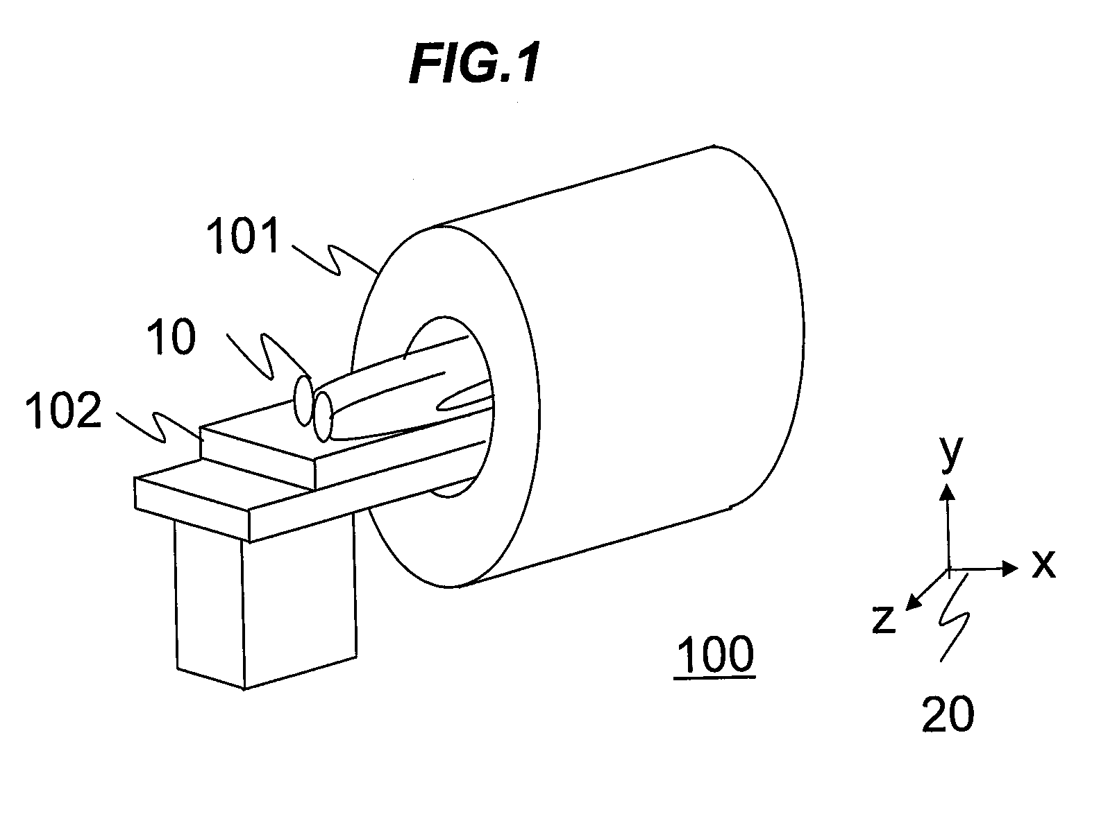
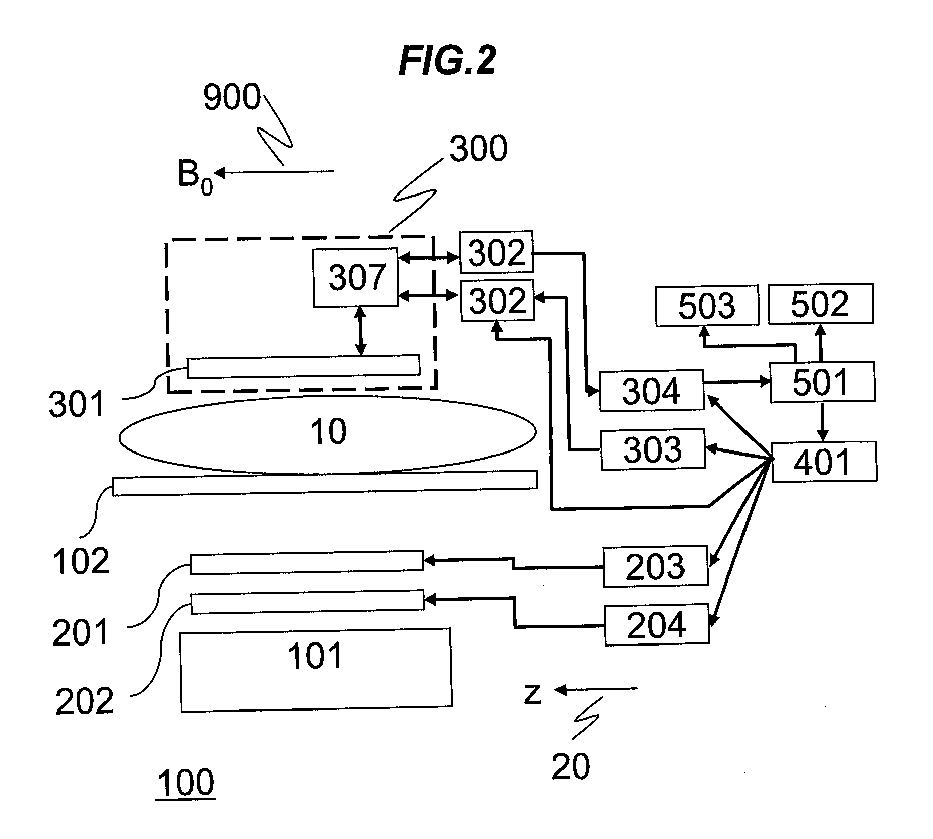
[0081]First, the total configuration of an MRI device according to this embodiment will be explained. FIG. 1 shows an external view of an MRI device according to this embodiment, and in the drawing, the direction of the z-axis of a coordinate system 20 is the direction of static magnetic field. The MRI device 100 according to this embodiment is provided with a horizontal magnetic field magnet 101, and a patient table 102. A test subject 10 is inserted into a space for imaging in a bore of the magnet 101 in a state of being laid down on the patient table 102, and subjected to imaging. Hereafter, in this specification, the direction of the static magnetic field is defined as the z-direction, the direction perpen...

second embodiment

[0157]Next, the second embodiment of the present invention will be explained. The MRI device of this embodiment is basically the same as that of the first embodiment. However, shapes of the RF shield, the first RF coil, and the second RF coil provided in the transceive coil are different. Hereafter, configurations different from those of the first embodiment will be explained. Also in this embodiment, it is supposed that the direction of the static magnetic field 900 generated by the magnet 101 of the horizontal magnetic field type is the same as the z-axis direction of the coordinate system 20.

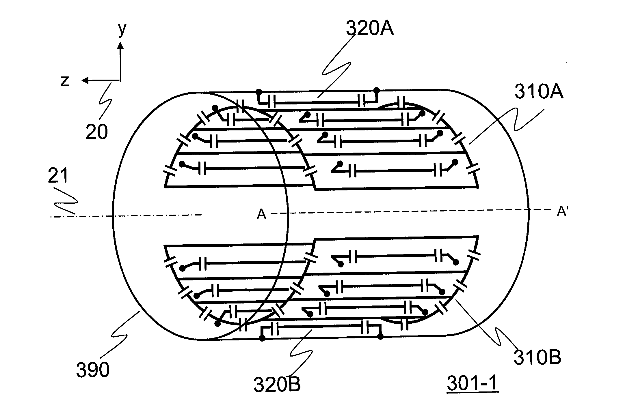
[0158]FIGS. 17A and 17B are drawings for explaining the configuration of a transceive coil 301-4 of this embodiment. FIG. 17A shows the transceive coil 301-4 obliquely seen from the side, and FIG. 17B shows the transceive coil 301-4 seen in the direction of the central axis 21. The first RF coils 310 (310A, 310B) and the second RF coils 320 (320A, 320B) are disposed so that the plane of symme...

third embodiment

[0188]Next, the third embodiment of the present invention will be explained. The MRI device of this embodiment is basically the same as that of the first embodiment. However, in the MRI device of this embodiment, a transmit coil and a receive coil are separately disposed. Hereafter, configurations different from those of the first embodiment will be mainly explained. Also in this embodiment, it is supposed that the direction of the static magnetic field 900 generated by the magnet 101 of the horizontal magnetic field type is the same as the z-axis direction of the coordinate system 20.

[0189]FIG. 22 is a block diagram showing a schematic configuration of an MRI device 100-5 according to this embodiment. The MRI device 100-5 according to this embodiment basically has the same configurations as those of the MRI device 100 according to the first embodiment. However, since it is separately provided with a transmit coil 305 and a receive coil 306, it is not provided with the RF signal div...


PUM


Abstract

There is provided a technique for securing a large examination space in a tunnel type MRI device without inviting increase of manufacturing cost and without significantly reducing irradiation efficiency or uniformity of the irradiation intensity distribution in an imaging region. Between rungs of a partially cylindrical RF coil, which coil corresponds to a cylindrical RF coil of which part is removed, there are disposed half-loops generating magnetic fields, which are synthesized with magnetic fields generated by loops constituted by adjacent rungs of the partially cylindrical RF coil and rings connecting the rungs to generate a circularly polarized or elliptically polarized magnetic field. Further, high-frequency signals of the same reference frequency having a desired amplitude ratio and phase difference are supplied to the partially cylindrical RF coils and half-loops.

Description

TECHNICAL FIELD[0001]The present invention relates to a magnetic resonance imaging (MRI) device and a high-frequency coil for irradiating electromagnetic waves and detecting magnetic resonance signals.BACKGROUND ART[0002]An MRI device is a medical diagnostic imaging apparatus, which induces magnetic resonance in nuclear spins in an arbitrary section of a test subject, and provides a tomogram for the section from generated magnetic resonance signals. When a high-frequency magnetic field is irradiated on a test subject rested in a static magnetic field with a high-frequency coil (RF coil) with applying a gradient magnetic field, nuclear spins of atomic nuclei in the test subject, for example, hydrogen nuclei, are excited, and when the excited nuclear spins return to the equilibrated state, circularly polarized magnetic fields are generated as magnetic resonance signals. These signals are detected with an RF coil and subjected to signal processing to visualize hydrogen nucleus distribu...

Claims


Application Information

Patent Timeline
Patent Type & Authority Applications(United States)
IPC IPC(8): G01R33/34G01R33/48
CPCG01R33/34076G01R33/3678G01R33/3657G01R33/3453G01R33/34053G01R33/34046
Inventor SOUTOME, YOSHIHISAHABARA, HIDETABITO, YOSHITAKATAKEUCHI, HIROYUKITAKAHASHI, TETSUHIKOOCHI, HISAAKI
Owner FUJIFILM HEALTHCARE CORP
Why Eureka
Try Eureka