Drawer type switch cabinet

A switch cabinet and drawer type technology, applied in the field of electrical cabinets, can solve the problem that the drawer cannot be matched with the rear bottom plate.

Active Publication Date: 2020-10-23
宁波功成电气有限公司
View PDF8 Cites 1 Cited by
  • Summary
  • Abstract
  • Description
  • Claims
  • Application Information

AI Technical Summary

Problems solved by technology

[0004] Aiming at the defect in the prior art that the drawer cannot cooperate with the rear bottom plate more stably when in use, the present invention provides a drawer-type switchgear

Method used


Image

  • Drawer type switch cabinet
  • Drawer type switch cabinet
  • Drawer type switch cabinet

Examples


Embodiment 1

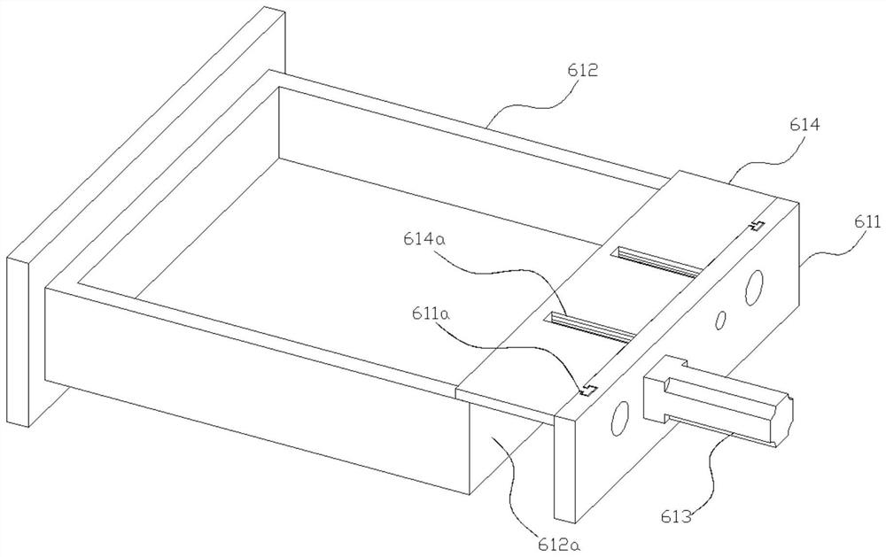
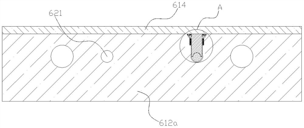
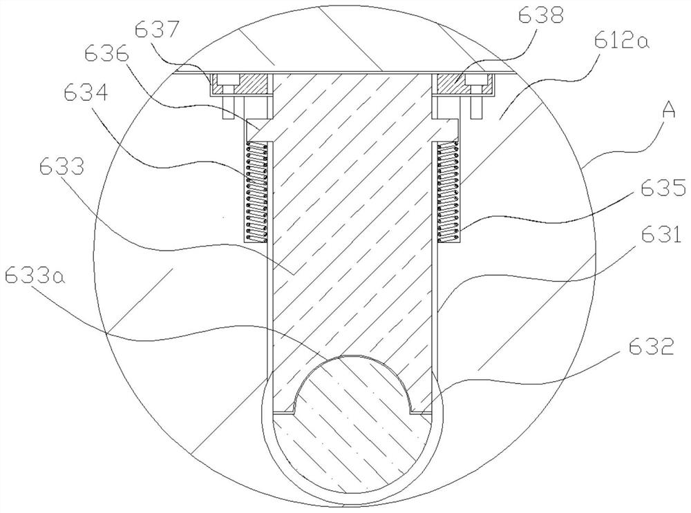
[0046] Such as Figure 1-9 As shown, the present embodiment provides a drawer-type switch cabinet, including a cabinet body, a rear bottom plate 611 fixedly connected with the cabinet body is provided in the cabinet body, and a drawer 612 located in the cabinet body is provided on one side of the rear bottom plate 611; 611 is provided with an electric push rod 613 on the end face away from the drawer 612, and the piston rod of the electric push rod 613 passes through the rear bottom plate 611 and can move toward the drawer end; the drawer 612 includes a rear side plate 612a close to the rear bottom plate 611, and There is a rear side plate through hole 621 that fits in clearance with the end of the piston rod of the electric push rod 613, and the rear side plate 612a is provided with a first elastic member that is located above the rear side plate through hole 621 and communicates with the rear side plate through hole 621 Mounting cavity 631, the end of the piston rod of the e...

Embodiment 2

[0065] Such as Figure 10-20 As shown, this embodiment provides a guide rail device, which includes a guide rail body 510, the longitudinal section of which is an "L" shape; The upper end of the 511 is provided with a mounting portion 512 perpendicular to the connecting portion 511. The mounting portion 512 is provided with a chute 512a. Block 512b; one end of the connecting portion 511 is provided with a first gear mounting cavity 521, and the first gear mounting cavity 521 is provided with a first gear 522 that can rotate along the sliding direction of the chute 512a; the bottom surface of the mounting portion 512 is installed with the first gear The cavities 521 communicate with each other, and the bottom end of the second slider 512b is provided with a second rack 531 matched with the first gear 522 .

[0066] Through the setting of the guide rail body 510, the first gear 522 and the second rack 531 in this embodiment, the connecting part 511 can be installed on the side ...

Embodiment 3

[0086] Such as Figure 1-20 As shown, this embodiment provides a switch cabinet, the cabinet body includes the guide rail drawer structure and the guide rail device described in Embodiment 1 and Embodiment 2, using the above structure, the cabinet body in this embodiment can be It is more stable and has better security when used.


PUM


Abstract

The invention relates to the technical field of electrical cabinets, and particularly discloses a drawer type switch cabinet which comprises a cabinet body, a rear bottom plate is arranged in the cabinet body, and a drawer is arranged on one side of the rear bottom plate. An electric push rod is arranged on the rear bottom plate, the drawer comprises a rear side plate, a rear side plate through hole is formed in the rear side plate, a first elastic piece mounting cavity is formed in the rear side plate, a first arc-shaped groove is formed in the electric push rod, a first elastic piece is arranged in the first elastic piece mounting cavity, and a second arc-shaped groove is formed in the lower end of the first elastic piece; a baffle is connected to the rear bottom plate, and the end, extending out of the rear side plate, of the first elastic piece is provided with an inclined face used for being matched with the baffle to enable the second arc-shaped groove to abut against the first arc-shaped groove. According to the drawer type switch cabinet, circuit connection and disconnection between the drawer and the rear bottom plate are conveniently and easily achieved, and the stabilityof circuit connection and disconnection between the drawer and the rear bottom plate is improved; and meanwhile, the drawer is locked, and the cost for producing and manufacturing the cabinet body isreduced.

Description

technical field [0001] The invention relates to the technical field of electrical cabinets, in particular to a drawer type switch cabinet. Background technique [0002] The drawer-type switch cabinet is made of steel plate to make a closed shell, and the electrical components of the incoming and outgoing circuit are all installed in the drawer, which constitutes a functional unit that can complete a certain type of power supply task. The functional unit is separated from the bus bar or cable by a grounded metal plate or a plastic functional plate to form three areas: bus bar, functional unit and cable. There are also isolation measures between each functional unit. Drawer-type switchgear has high reliability, safety and interchangeability, and is a relatively advanced switchgear. Most of the switchgears currently produced are drawer-type switchgears. They are suitable for industrial and mining enterprises and high-rise buildings that require high reliability of power suppl...

Claims


Application Information

Patent Timeline
IPC IPC(8): H02B11/173H02B11/127H02B11/02
CPCH02B11/173H02B11/127H02B11/02
Inventor 张旋
Owner 宁波功成电气有限公司
Why Eureka
Try Eureka