Rowing machine with adjustable water tank angle
A rowing machine and water tank technology, applied in the field of fitness equipment, can solve the problems of high maintenance cost, complex equipment structure, wear and tear, etc., and achieve the effects of reducing inertia, improving rowing experience, good exercise effect and mechanical balance
- Summary
- Abstract
- Description
- Claims
- Application Information
AI Technical Summary
Problems solved by technology
Method used
Image
Examples
Embodiment 1
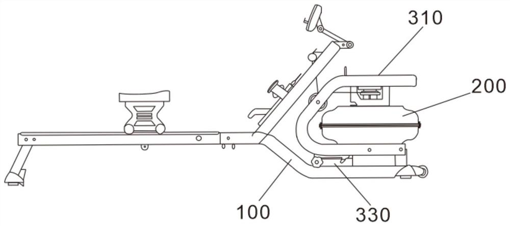
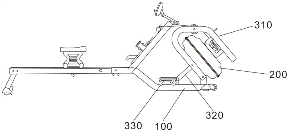
[0059] The angle adjustment mechanism includes a support rod 320 and an adjustment rod 330, the adjustment rod 330 is fixed on the chassis 100, the adjustment rod 330 is distributed with several gear slots 331, one end of the support rod 320 is connected to The water tank 200 is hinged, and the other end is fixed in the gear slot 331 on the adjusting rod 330 .
[0060] In specific implementation, such as Figure 4 As shown, the angle adjustment mechanism includes a support rod 320 and an adjustment rod 330, the adjustment rod 330 is horizontally fixed on the chassis 100, the adjustment rod 330 is distributed with several gear slots 331, one end of the support rod 320 is hinged on the water tank 200, and the other One end is located in the gear slot 331 on the adjustment rod 330; when in use, according to the needs, first move one end of the support rod 320 on the adjustment rod 330, so that one end of the support rod 320 is in a different gear slot 331, through the support rod...
Embodiment 2
[0062] The angle adjustment mechanism also includes a bracket 310 for fixing the water tank 200, the water tank 200 is hinged to the underframe 100 through one end of the bottom of the bracket 310, and the end of the support rod 320 away from the adjustment rod 330 is connected to the bracket 310. hinged.
[0063] In specific implementation, such as figure 1 and figure 2 As shown, the angle adjustment mechanism includes a bracket 310 for fixing the water tank 200, a support rod 320 and an adjustment rod 330. The water tank 200 is hinged to the bottom frame 100 through one end of the bottom of the bracket 310, and the adjustment rod 330 is fixed on the bottom frame 100. The adjustment rod 330 is distributed with several gear slots 331, one end of the support rod 320 is hinged with the bracket 310, and the other end is fixed in the gear slot 331 on the adjustment rod 330; when in use, first move the support rod on the adjustment rod 330 One end of 320, so that one end of supp...
Embodiment 3
[0065] The angle adjustment mechanism is a telescopic rod 321 , the movable end of the telescopic rod 321 is hinged to the water tank 200 , and the other end is hinged to the bottom frame 100 .
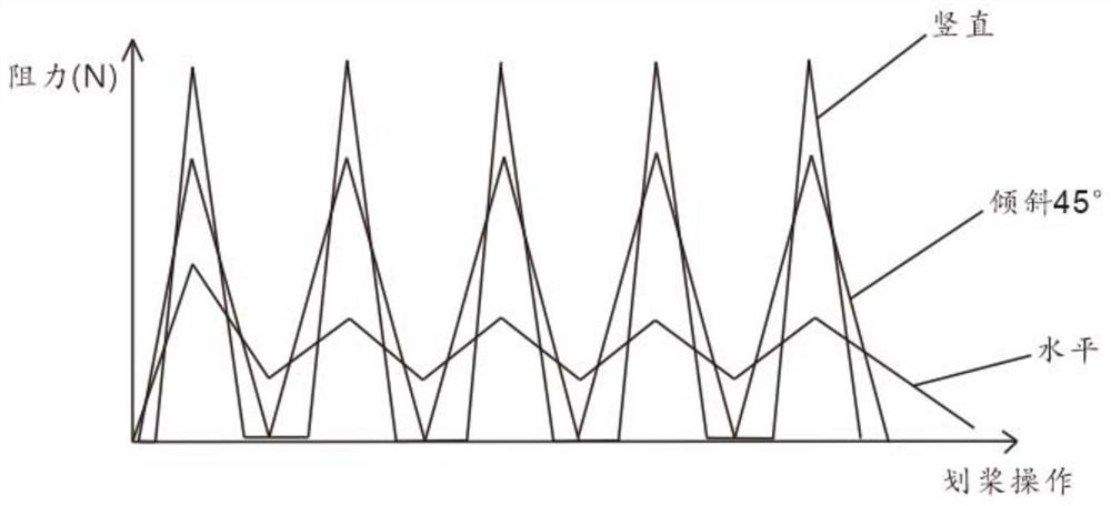
[0066] In specific implementation, such as Figure 5 As shown, the angle adjustment mechanism is a telescopic rod 321, which is specifically one of a hydraulic cylinder, a pneumatic cylinder, and an electric push rod; The extension or contraction of 321 drives the water tank 200 to rotate around its hinge with the bottom frame 100, thereby changing the placement angle of the water tank 200 and realizing the adjustment of resistance.
PUM
 Abstract
Description
Claims
Application Information
 - R&D
- Intellectual Property
- Life Sciences
- Materials
- Tech Scout
- Unparalleled Data Quality
- Higher Quality Content
- 60% Fewer Hallucinations
Browse by: Latest US Patents, China's latest patents, Technical Efficacy Thesaurus, Application Domain, Technology Topic, Popular Technical Reports.
© 2025 PatSnap. All rights reserved.Legal|Privacy policy|Modern Slavery Act Transparency Statement|Sitemap|About US| Contact US: help@patsnap.com


