
Warning device for electric power construction

A warning device and electric power construction technology, applied in the field of electric power, can solve problems such as low warning strength and high risk, and achieve the effects of improving stability, increasing friction, and improving warning effects

Inactive Publication Date: 2020-10-30
宋允华
View PDF0 Cites 2 Cited by
  • Summary
  • Abstract
  • Description
  • Claims
  • Application Information

AI Technical Summary

Problems solved by technology

[0003] The existing warning devices for electric power construction can only warn people by observing the warning signs, and the warning strength is relatively low. When people enter the construction site by mistake without noticing the warning signs, there is a high risk

Method used


Image

  • Warning device for electric power construction
  • Warning device for electric power construction
  • Warning device for electric power construction

Examples


Embodiment 1

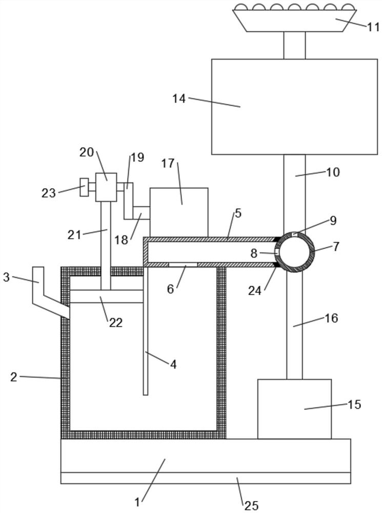
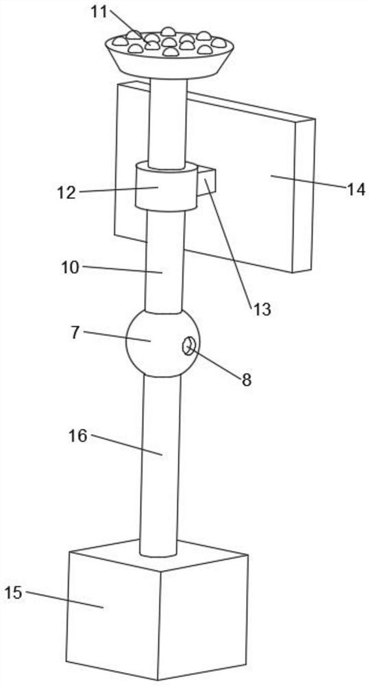
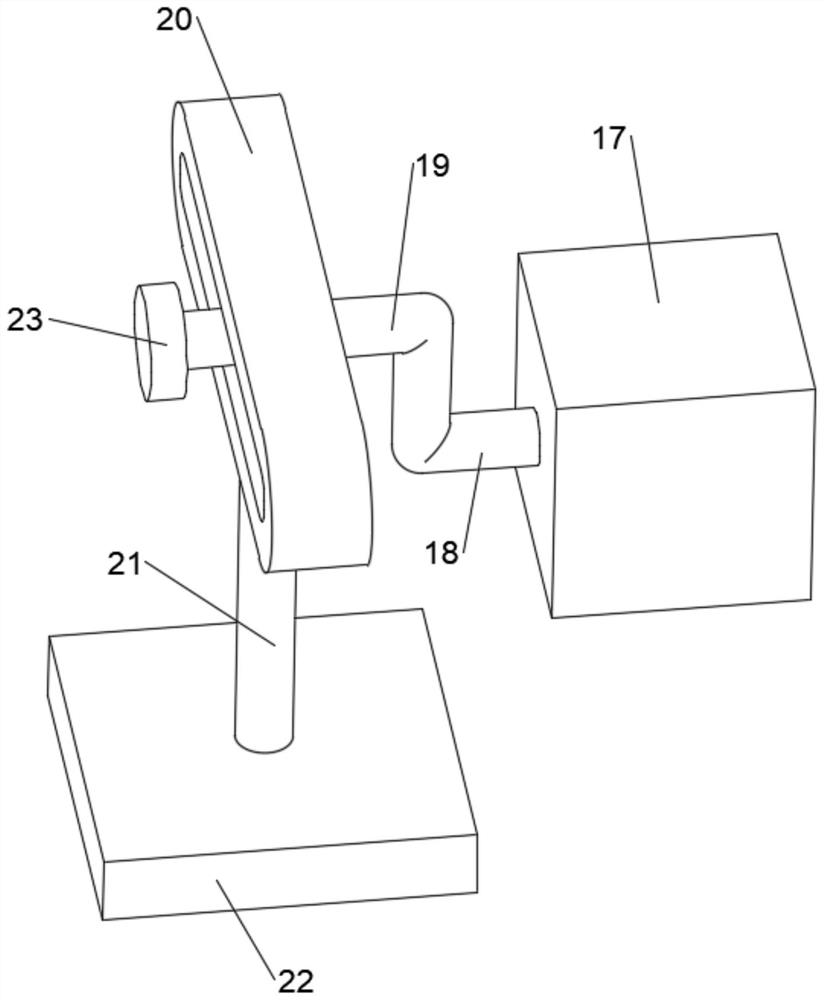
[0021] See Figure 1-3 In an embodiment of the present invention, a warning device for electric power construction includes a base 1, a water tank 2 is provided at the upper end of the base 1, a water inlet pipe 3 is provided at the left end of the water tank 2, and a partition 4 is fixedly connected to the top wall of the water tank 2, The top of the water tank 2 is provided with a water pipe 5, which is located to the right of the partition 4, the lower end of the water pipe 5 is provided with a through hole 6 to communicate with the water tank 2, the right end of the water pipe 5 is provided with a water spray device, and the water pipe 5 is provided with a squeezing device The squeezing device is located on the left side of the partition 4, and water is added to the water tank 2 through the water inlet pipe 3. The water on the left side of the partition 4 is squeezed by the squeezing device. The water enters the water pipe 5 through the through hole 6 and then passes through...

Embodiment 2

[0028] In order to prevent water leakage at the connection between the water pipe 5 and the hollow ball 7, this embodiment is further improved on the basis of Embodiment 1. The improvement is: the water pipe 5 is provided with a waterproof jacket 24 at the right end. The hollow balls 7 are in close contact and play a waterproof role.

[0029] The working principle of this embodiment is: in order to prevent water leakage at the connection between the water pipe 5 and the hollow ball 7, a waterproof jacket 24 is provided at the right end of the water pipe 5, and the waterproof jacket 24 can make it come into close contact with the hollow ball 7 for waterproofing Role.

[0030] To sum up, by setting up a squeezing device, the water is squeezed into the water inlet pipe 5 through the through hole 6 and then sprayed out through the water spray device to remind people that construction is underway here, warn people not to approach here, and improve the warning device’s effectiveness. Wa...


PUM


Abstract

The invention discloses a warning device for electric power construction. The device includes a base, a water tank is arranged at the upper end of the base; a water inlet pipe is arranged at the leftend of the water tank; a partition plate is fixedly connected to the top wall in the water tank; a water pipe is arranged at top end of the water tank, the water pipe is located on the right of the partition plate, a through hole is formed in the lower end of the water pipe and communicated with the water tank, a water spraying device is arranged at the right end of the water pipe, an extrusion device is arranged on the water pipe and located on the left side of the partition plate, water is added into the water tank through the water inlet pipe and extruded through the extrusion device, and the water enters the water pipe through the through hole and then the water is sprayed out through the water spraying device. By arranging the extrusion device, the water is extruded into the water inlet pipe through the through hole and then sprayed out through the water spraying device, people are reminded that construction is conducted at the position, people are warned not to get close to the position, and the warning effect of the warning device is improved.

Description

Technical field [0001] The invention relates to the field of electric power, in particular to a warning device for electric power construction. Background technique [0002] In order to prevent personnel from accidentally entering the live area and accidentally touching the live equipment and causing personal injury or death when the power company constructs, rebuilds and expands in some sites, it is necessary to place warning signs in the construction area. The power construction warning signs have the function of warning and reminding people. Make people stay away from dangerous areas, facilitating people's life and safety. [0003] The existing warning device for electric power construction can only warn people by observing the warning sign, and the warning strength is low. When people stray into the construction site without paying attention to the warning sign, it has a higher risk. Summary of the invention [0004] The object of the present invention is to provide a warning d...

Claims


Application Information

Patent Timeline
Patent Type & Authority Applications(China)
IPC IPC(8): E01F9/65
CPCE01F9/65
Inventor 宋允华
Owner 宋允华
Learn More