Propagation link marking method and device

A technology for disseminating links and links, applied in the field of communication, can solve the problems that routers cannot distinguish routes, the backbone network cannot effectively manage A, and subnet 1 cannot filter, etc.

Active Publication Date: 2020-10-30
北京华三通信技术有限公司
8 Cites 0 Cited by

AI-Extracted Technical Summary

Problems solved by technology

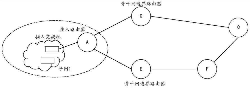
In this network, the backbone network needs to filter the routes about subnet 1 released by A, but the backbone network cannot effectively manage A, and it can only configure the routers (including G and E) included in the backbone network. manage
[0004] At this time, the route about subnet 1 advertised by A does not carry a routin...

Abstract

The invention provides a propagation link marking method and device. The method is applied to a first router, the first router operates an OSPFv3 protocol, the first router and a second router are neighbors to each other, and the method comprises the following steps that a link marking value of a first specified link is obtained; and a first link state advertisement LSA is sent to the second router, wherein the first LSA comprises the link mark value, so that when the second router starts a route filtering mode or the second router is an area boundary router ABR, a specified route is determined according to the link mark value, and a transmission path corresponding to the specified route comprises the first specified link.

Application Domain

Data switching networks

Technology Topic

TelecommunicationsRouter +6

Image

  • Propagation link marking method and device
  • Propagation link marking method and device
  • Propagation link marking method and device

Examples

  • Experimental program(1)

Example Embodiment

[0022] Exemplary embodiments will be described in detail herein, examples of which are illustrated in the accompanying drawings. Where the following description refers to the drawings, the same numerals in different drawings refer to the same or similar elements unless otherwise indicated. The embodiments described in the following exemplary embodiments are not intended to represent all embodiments consistent with this application. Rather, they are merely examples of apparatus and methods consistent with some aspects of the present application as recited in the appended claims.
[0023] The terminology used in this application is for the purpose of describing particular embodiments only and is not intended to limit the application. As used in this application and the appended claims, the singular forms "a," "the," and "the" are intended to include the plural forms as well, unless the context clearly dictates otherwise. It will also be understood that the term "and/or" as used herein refers to and includes any and all possible combinations of one or more of the corresponding listed items.
[0024] It should be understood that although the terms first, second, third, etc. may be used in this application to describe various information, such information should not be limited by these terms. These terms are only used to distinguish the same type of information from each other. For example, the first information may also be referred to as the second information, and similarly, the second information may also be referred to as the first information without departing from the scope of the present application. Depending on the context, the word "if" as used herein can be interpreted as "at the time of" or "when" or "in response to determining."
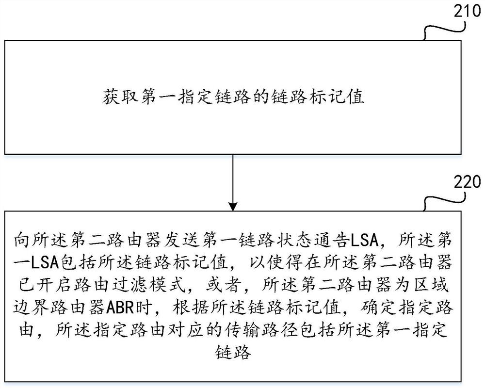
[0025] The method for propagating link labels provided by the embodiments of the present application will be described in detail below. see figure 2 , figure 2 This is a flowchart of a method for propagating a link label according to an embodiment of the present application. The method is applied to the first router. The first router runs the OSPFv3 protocol. The first router and the second router are neighbors to each other. The method for propagating a link label provided by this embodiment of the present application may include the following steps.
[0026] Step 210: Obtain the link tag value of the first designated link.
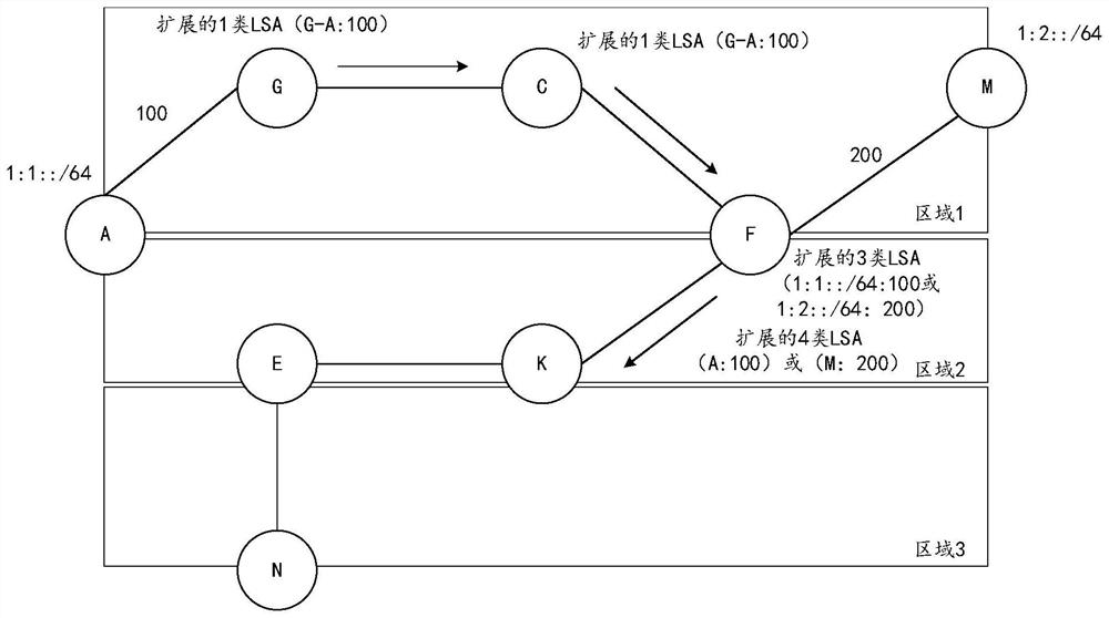
[0027] Specifically, as image 3 As shown, a schematic diagram of a network for disseminating link tag values ​​in an OSPFv3 network provided by an embodiment of the present application. The OSPFv3 network includes three areas, namely Area 1, Area 2, and Area 3. Node A, node G, node C, node F, and node M are in area 1; node A, node E, node K, and node F are in area 2; node E and node N are in area 3. Node A, Node F, and Node E are ABRs, and Node A and Node M are also ASBRs to import external routes.
[0028] In this embodiment of the present application, the first router may serve as any one of the above-mentioned nodes.
[0029] Wherein, the specific process of obtaining the link tag value of the first designated link includes the following situations:
[0030] Case 1: The first router receives a link configuration instruction input by a user, where the link configuration instruction includes an interface identifier and a link tag value. For example, the link configuration instruction may be specifically in the format of "ospfv3 link-tag tag". According to the interface identifier, the first router determines the first designated link connected to the interface indicated by the interface identifier.
[0031] like image 3 As shown, the first router is node G. At this point, the user inputs a link configuration command in the interface view displayed by node G. The interface identifier represents an interface included in the node G. A communication link is established with node A through the interface node G. According to the interface identifier, node G determines the first designated link connected to node A. At the same time, node G marks the first designated link with a link label value.
[0032] or,
[0033] In the second case, the first router acts as any node except node G, that is, the first router is not a node that directly receives the link configuration instruction input by the user, for example, node C.
[0034] It can be understood that in an OSPFv3 network, nodes that are neighbors in the same area advertise LSAs to each other. ), which is an extended Type 1 LSA. For example, node G and node C issue LSAs to each other in area 1.
[0035] As an ABR node, it advertises LSAs in a certain area to another area. For example, node F. After receiving the E-Router-LSA in the area 1 issued by the node C, the node F issues the LSA to the node K in the area 2. The LSA is specifically an extended inter-area prefix link state advertisement (English: Extended- Inter-Area-Prefix-LSA, referred to as: E-Inter-Area-Prefix-LSA), that is, extended Type 3 LSA, extended inter-area router link state advertisement (English: Extended-Inter-Area-Router- LSA, abbreviated as E-Inter-Area-Router-LSA), is an extended Type 4 LSA.
[0036] To sum up, LSAs have different types according to different roles of nodes.
[0037] In the second case, the first router receives a second LSA sent by a third router that is a neighbor of the first router, where the second LSA includes a link attribute and a link label value. Based on the link attributes, the first router determines the first designated link.
[0038] like image 3 As shown, the first router is node C. Node C receives the E-Router-LSA advertised by node G, where the E-Router-LSA includes link attributes and link label values. If node C enables the route filtering mode, then according to the link attribute, node C determines that the first designated link is the link between node G and node A. At the same time, node C marks the first designated link with a link label value.
[0039] like image 3 As shown, the first router is node F. Node F receives the E-Router-LSA advertised by node C, where the E-Router-LSA includes link attributes and link label values. According to the link attribute, node F determines that the first designated link is the link between node G and node A. At the same time, node F marks the first designated link with a link label value.
[0040] like image 3 As shown, the first router is node K. Node K receives the E-Inter-Area-Prefix-LSA and E-Inter-Area-Router-LSA advertised by node F. The E-Inter-Area-Prefix-LSA and E-Inter-Area-Router-LSA also include Link tag value. It can be understood that the E-Inter-Area-Prefix-LSA further includes the address attribute of the designated address prefix; the E-Inter-Area-Router-LSA also includes the device attribute of the designated router.
[0041] If node K turns on the route filtering mode, node K marks the route to the specified address prefix with the link label value, or the node K marks the route to the specified router with the link label value.
[0042] It should be noted that if the node has turned on the route filtering mode, or if the node is an ABR, before marking the route with the link label value, the node first distinguishes the designated route through the designated link, and then uses the link label to mark the route. The value marks the specified route. The specific identification process will be described later.
[0043] If the node does not enable the route filtering mode, or when the node is a non-ABR, after receiving the second LSA, the node directly executes step 220, and does not execute the above process of identifying the specified route.
[0044] Step 220: Send a first link state advertisement LSA to the second router, where the first LSA includes the link label value, so that the second router has enabled the route filtering mode, or, the first LSA When the second router is an area border router ABR, a designated route is determined according to the link tag value, and the transmission path corresponding to the designated route includes the first designated link.
[0045] Specifically, after the first router obtains the link label value of the first designated link, the first router generates the first LSA. The first LSA includes a link label value. The first router sends the first LSA to the second router. After receiving the first LSA, the second router obtains the link label value therefrom. According to the link tag value, a designated route is determined, wherein the transmission path corresponding to the designated route includes the first designated link.
[0046] Further, the first router generates and sends the first LSA to the second router in different ways according to its own role, and the specific process includes the following multiple situations:
[0047] Case 1: The first router obtains the link label value in the form of receiving a link configuration instruction input by the user, and the first router generates and sends the first LSA to the second router. Wherein, the first LSA includes an extended type 1 LSA (ie, E-Router-LSA). This extended Type 1 LSA includes link attributes as well as link tag values.
[0048] like image 3 As shown, the first router is node G. According to the description of step 210, node G obtains the link flag value according to the link configuration instruction input by the user. Meanwhile, according to the interface identifier, node G determines that the link connected with node A is the first designated link. Node G marks the first designated link with a link label value. Node G generates an E-Router-LSA, where the E-Router-LSA includes link attributes and link label values. Node G sends the E-Router-LSA to Node C.
[0049] like image 3 As shown, the first router is node F. Node F obtains the link tag value according to the link configuration instruction input by the user. Meanwhile, according to the interface identifier, the node F determines that the link connected with the node M is the first designated link. Node F marks the first designated link with a link label value. As an ABR, node F needs to transmit information such as addresses and routes in area 1 to nodes included in area 2. Node F generates extended type 3 LSAs (that is, E-Inter-Area-Prefix-LSA), or generates extended LSAs. Type 4 LSAs (ie, E-Inter-Area-Router-LSAs), the E-Inter-Area-Prefix-LSAs and E-Inter-Area-Router-LSAs include link label values ​​(links F-M tag value). Node F sends the E-Inter-Area-Prefix-LSA and E-Inter-Area-Router-LSA to node K.
[0050] It can be understood that the node F also performs a process similar to that of the node G to generate an E-Router-LSA, where the E-Router-LSA includes a link attribute and a link label value (the link label value of the link F-M). Node G sends the E-Router-LSA to Node C.
[0051] Case 2: When the first router is an ABR, or when the first router has turned on the route filtering mode, the first router determines whether the designated address prefix is ​​recorded locally, and the designated address prefix arrives via the first designated link, or the first router It is judged whether the identifier of the designated router is recorded locally, and the designated router represented by the identifier of the designated router is reached via the first designated link. If the local record specifies the address prefix, or the local record specifies the router identifier, the first router generates the first LSA, and sends the first LSA to the second router.
[0052] The first LSA includes an extended Type 1 LSA (ie, E-Router-LSA), or the first LSA includes an extended Type 3 LSA (ie, E-Inter-Area-Prefix-LSA), or, the first LSA LSAs include Extended Type 4 LSAs (ie, E-Inter-Area-Router-LSAs). The extended type 1 LSA includes link attributes and link label values; the extended type 3 LSA includes address attributes of the specified address prefix and link label values, and the extended type 4 LSA includes the device attributes and link label values ​​of the specified router tag value.
[0053] like image 3 As shown, the first router is node F. Node A imports external routes, and node A accesses a subnet. The IPv6 address prefix for this subnet is 1:1::/64.
[0054] According to the description of step 210, node F receives the E-Router-LSA advertised by node C, where the E-Router-LSA includes link attributes and link label values. According to the link attribute, node F determines that the first designated link is the link between node G and node A. At the same time, node F marks the first designated link with a link label value.
[0055] Since node F is located at the boundary of two areas, node F as an ABR needs to transmit information such as addresses and routes in area 1 to nodes included in area 2. At this point, node F determines whether the designated address prefix (for example, IPv6 address prefix 1:1::/64) is recorded locally, and the designated address prefix is ​​reached via the G-A link, or node F determines whether the designated router is recorded locally (in this case). In the application embodiment, the designated router specifically refers to the ASBR, for example, the identifier of the node A), and the designated router represented by the identifier of the designated router is reached via the G-A link.
[0056] If the local record of node F specifies the address prefix, or the local record of node F specifies the router identifier, then node F generates E-Inter-Area-Prefix-LSA, E-Inter-Area-Router-LSA, and the E-Inter-Area- The Prefix-LSA includes the address attribute of the specified address prefix and the link label value; the E-Inter-Area-Router-LSA includes the device attribute of the specified router and the link label value. Node F sends E-Inter-Area-Prefix-LSA and E-Inter-Area-Prefix-LSA to node K.
[0057] Further, the specific process of judging whether the node F records the designated address prefix locally, or whether it records the identifier of the designated router locally is:
[0058] Through the shortest path tree algorithm, node F uses itself as the root node to establish a shortest path tree when calculating a route, and the shortest path tree also includes multiple child nodes. From the shortest path tree, node F determines whether there is a child node with a link label value. If so, the node F judges whether the child node has a designated address prefix (for example, the IPv6 address prefix 1:1::/64), or the node F judges whether the child node is a designated router (in this embodiment of the present application, the designated router Specifically ASBR, eg node A). If the child node has a designated address prefix, or the child node is a designated router, node F marks the route reaching the designated address prefix as the link label value, or marks the route reaching the designated router as the link label value.
[0059] like Figure 4 shown, Figure 4 A schematic diagram of the shortest path tree of an OSPFv3 network provided in the embodiment of the present application; in Figure 4 Among them, node F is the root node, other nodes are child nodes, and the connection between the nodes represents the link between the routers. As can be seen from the foregoing, the G-A link is the first designated link, and the link label value is 100. Node F marks the route to the IPv6 address prefix 1:1::/64 as 100, and the route to node A as 100 .
[0060] Similarly, if the node C has enabled the route filtering mode, the node C also performs the aforementioned process of the node F distinguishing the specified route.
[0061] Scenario 3: When the first router is an ABR, or the first router has turned on the route filtering mode, the first router determines whether the designated address prefix is ​​recorded locally, and the designated address prefix is ​​reached by the third router, or the first router determines whether the local address prefix is ​​recorded. is to record the identifier of the designated router, and the designated router represented by the identifier of the designated router is reached via the third router. If the local record specifies the address prefix, or the local record specifies the router identifier, the first router generates the first LSA, and sends the first LSA to the second router.
[0062] Wherein, the first LSA includes an extended type 3 LSA (ie, E-Inter-Area-Prefix-LSA), or the first LSA includes an extended type 4 LSA (ie, E-Inter-Area-Router-LSA). The extended type 3 LSA includes the address attribute of the specified address prefix and the link label value, and the extended type 4 LSA includes the device attribute of the specified router and the link label value.
[0063] like image 3As shown, the first router is node E. Node A imports external routes, and node A accesses a subnet, etc. The IPv6 address prefix for this subnet is 1:1::/64.
[0064] According to the description of step 210, node E receives the E-Inter-Area-Prefix-LSA and E-Inter-Area-Router-LSA and advertised by node F and forwarded by node K. The E-Inter-Area-Prefix-LSA includes the address attribute of the specified address prefix and the link label value; the E-Inter-Area-Router-LSA includes the device attribute of the specified router and the link label value.
[0065] Since node E is located at the boundary of two areas, node E, as an ABR, needs to transmit the acquired information such as addresses and routes in area 1 to nodes included in area 3. At this time, node E judges whether the designated address prefix (for example, IPv6 address prefix 1:1::/64) is recorded locally, and the designated address prefix is ​​reached by node F, or node E judges whether the designated router is recorded locally (in this application In the embodiment, the designated router specifically refers to the ASBR, for example, the identifier of the node A), and the designated router represented by the identifier of the designated router is reached via the node F.
[0066] If the local record of node E specifies the address prefix, or the local record of node E specifies the router identifier, then node E generates E-Inter-Area-Prefix-LSA, E-Inter-Area-Router-LSA, and the E-Inter-Area- The Prefix-LSA includes the address attribute of the specified address prefix and the link label value; the E-Inter-Area-Router-LSA includes the device attribute of the specified router and the link label value. Node F sends E-Inter-Area-Prefix-LSA and E-Inter-Area-Prefix-LSA to node K.
[0067] Further, node E determines whether the designated address prefix is ​​recorded locally, or the specific process of determining whether the local is recording the identifier of the designated router is:
[0068] Through the shortest path tree algorithm, node E uses itself as a root node to establish a shortest path tree when calculating a route, and the shortest path tree also includes multiple child nodes. From the shortest path tree, node E determines whether there is a first child node with a link tag value. If so, node E judges whether the first child node has a designated address prefix (for example, IPv6 address prefix 1:1::/64), or node E judges whether the first child node is a designated router (in this embodiment of the present application) , the designated router specifically refers to the ASBR, for example, node A). If the first child node has a designated address prefix, or the first child node is a designated router, node E determines whether the path to the first child node passes through the second child node representing the third router. Node E marks the route to the specified address prefix as a link label value if the path to the first child passes through the second child representing the third router, or node E marks the route to the specified router as a link tag value.
[0069] like Figure 5 shown, Figure 5 A schematic diagram of the shortest path tree of another OSPFv3 network provided in the embodiment of the present application; Figure 5 Among them, node E is the root node, other nodes are child nodes, and the connection between the nodes represents the link between each router. As can be seen from the foregoing, the G-A link is the first designated link, and the link label value is 100. Node E will reach the IPv6 address prefix 1:1::/64 and the route through node F is marked as 100, and will reach node A and Routes via node F are labeled 100.
[0070] Similarly, if the node K has enabled the route filtering mode, the node K also performs the aforementioned process of the node F distinguishing the designated route.
[0071] It should be noted that if Image 6 shown, Image 6 A schematic diagram of a shortest path tree of still another OSPFv3 network provided by the embodiment of the present application. When node P calculates the route, it uses itself as the root node to generate the shortest path tree. Since the label value of the P-R link is 100, and the child nodes of this link are R and Y, node P uses the link label value of 100 to label the route to R and Y. (If R and Y have the IPv6 address prefix of the access subnet, node P uses the link tag value of 100 to mark the route to the IPv6 address prefix; if R and Y are ASBR, then node P uses the link tag value of 100 to mark the arrival route ASBR routing)
[0072] In the path from the node P to the child node X, the Q-S link and the S-X link have different link label values, which are the link label value of 200 and the link label value of 300, respectively. Since the S-X link is closest to node X, node P selects a link label value of 300 to label the route to X. In the path from node P to child node T, the closest link of ion node T carrying the link tag value is Q-T. There are two or more equivalent links in the Q-T link, which are the link tag value of 400 and the link tag value of 500, respectively. Since the link tag value of 400 is less than the link tag value of 500, node P selects the link tag value of 400 to mark the route to node T.
[0073] It should be noted that the links between nodes are directional, and a link tag value corresponds to a link. For example, in Image 6 , the link tag value of the P-R link is 100, and the link tag value of the R-P link is 200. When the node P calculates the route, it needs to select the corresponding link label value to mark the route according to the direction of the link. For example, when node P calculates the route to Y, it selects the link label value of the P-R link to mark the route to Y, but not the link label value of the R-P link.
[0074] Case 4: When the first router does not enable the route filtering mode, or when the first router is not an ABR, the first router forwards the first LSA sent by the third router to the second router.
[0075] Wherein, the first LSA includes an extended type 1 LSA (ie, E-Router-LSA), or, the first LSA includes an extended type 3 LSA (ie, E-Inter-Area-Prefix-LSA), or, The first LSA includes an extended type 4 LSA (ie, E-Inter-Area-Router-LSA). The extended type 1 LSA includes link attributes and link label values; the extended type 3 LSA includes address attributes of the specified address prefix and link label values, and the extended type 4 LSA includes the device attributes and link label values ​​of the specified router tag value.
[0076] like image 3 As shown, the first router is node C. Node C receives the E-Router-LSA advertised by node G. If node C does not enable route filtering mode, or node C is a non-ABR, node C directly forwards the E-Router-LSA to its neighbor node F.
[0077] like image 3 As shown, the first router is node K. According to the description of step 210, node K receives the E-Inter-Area-Prefix-LSA and E-Inter-Area-Router-LSA advertised by node F, if node K does not enable route filtering mode, or node K is non-ABR, Then node K directly forwards E-Inter-Area-Prefix-LSA and E-Inter-Area-Prefix-LSA to its neighbor node E.
[0078] Therefore, by applying a method for propagating a link label provided by an embodiment of the present application, after acquiring the link label value of the first designated link, the first router sends the first link state advertisement LSA to the second router, and the first router sends the first link state advertisement LSA to the second router. An LSA includes a link label value, so that when the second router has turned on the route filtering mode, or when the second router is an area border router ABR, a designated route is determined according to the link label value, and the transmission path corresponding to the designated route includes the first designated link. In this way, the link tag value of a certain (or several) links is propagated in the OSPFv3 network, so that other routers in the network can identify the route propagated through this (or these) links, so as to realize route filtering, routing policy, etc. Network control behavior.
[0079] The following is a detailed description through an example. like image 3 As shown, the OSPFv3 network includes three areas, ie, area 1, area 2, and area 3. Node A, node G, node C, node F, and node M are in area 1; node A, node E, node K, and node F are in area 2; node E and node N are in area 3. Node A, Node F, and Node E are ABRs, and Node A and Node M are also ASBRs to import external routes.
[0080] In the same area, the link tag value is propagated between nodes:
[0081] Node G receives the link configuration instruction input by the user, and the G-A link is marked with a value of 100. Node G generates an E-Router-LSA, and the Router-Link TLV field describing the relevant link in the E-Router-LSA is filled with the Route-Tag Sub-TLV field. The Route Tag field included in the Route-Tag Sub-TLV field is filled with a link tag value of 100 for the G-A link.
[0082] Node G sends E-Router-LSA to Node C. If node C does not enable route filtering mode, or node C is a non-ABR, after receiving the E-Router-LSA sent by node G, node C does not change the contents of the E-Router-LSA, and continues to send the E-Router-LSA to its neighbor node F. E-Router-LSA.
[0083] In different regions, the link tag value is propagated between nodes:
[0084] The A-G link tag value 100, in the aforementioned manner, in the same area, the link tag value is propagated between nodes, and the link tag value of the G-A link is propagated to node F. Similarly, the node F receives the link configuration instruction input by the user, and the F-M link is marked with a value of 200. Subnet 1 is connected to node A, the IPv6 address prefix of subnet 1 is 1:1::/64, and subnet 2 is connected to node M, and the IPv6 address prefix of subnet 2 is 1:2::/64. Node A and Node M serve as ASBRs to import external routes.
[0085] Node F calculates that reaching subnet 1 (ie, IPv6 address prefix 1:1::/64) needs to go through the G-A link, and reaching node A (ie, ASBR) needs to go through the G-A link. Node F generates an E-Inter-Area-Prefix-LSA. The Inter-Area-Prefix TLV field in the E-Inter-Area-Prefix-LSA that describes the IPv6 address prefix 1:1::/64 includes the Route-Tag Sub-TLV field . The Route Tag field included in the Route-Tag Sub-TLV field is filled with a link tag value of 100 for the G-A link. At the same time, node F also generates an E-Inter-Area-Router-LSA, and the Inter-Area-Router TLV field describing the ASBR in the E-Inter-Area-Router-LSA includes the Route-Tag Sub-TLV field. The RouteTag field included in the Route-Tag Sub-TLV field is filled with a link tag value of 100 for the G-A link.
[0086]Node F calculates that reaching subnet 2 (ie, IPv6 address prefix 1:2::/64) needs to go through the F-M link, and reaching node M (ie, ASBR) needs to go through the F-M link. Node F generates an E-Inter-Area-Prefix-LSA. The Inter-Area-Prefix TLV field in the E-Inter-Area-Prefix-LSA that describes the IPv6 address prefix 1:2::/64 includes the Route-Tag Sub-TLV field . The Route Tag field included in the Route-Tag Sub-TLV field is filled with a link tag value of 200 for the F-M link. At the same time, node F also generates an E-Inter-Area-Router-LSA, and the Inter-Area-Router TLV field describing the ASBR in the E-Inter-Area-Router-LSA includes the Route-Tag Sub-TLV field. The RouteTag field included in the Route-Tag Sub-TLV field is filled with the link tag value 200 of the F-M link.
[0087] Node F sends E-Inter-Area-Prefix-LSA and E-Inter-Area-Router-LSA to node K. If node K does not enable route filtering mode, or node K is non-ABR, after node K receives E-Inter-Area-Prefix-LSA and E-Inter-Area-Router-LSA sent by node F, it does not - Area-Prefix-LSA and E-Inter-Area-Router-LSA include content to be changed, and continue to send the E-Inter-Area-Prefix-LSA and E-Inter-Area-Router-LSA to neighbor node E.
[0088] After node E receives the E-Inter-Area-Prefix-LSA and E-Inter-Area-Router-LSA sent by node K (the publisher is still node F), it calculates to reach subnet 1 (that is, IPv6 address prefix 1: 1::/64) and subnet 2 (ie, IPv6 address prefix 1:2::/64) need to go through node F; reaching ASBR (ie, node A, node M) needs to go through node F.
[0089] Node E generates an E-Inter-Area-Prefix-LSA. The Inter-Area-Prefix TLV field in the E-Inter-Area-Prefix-LSA that describes the IPv6 address prefix 1:1::/64 includes the Route-Tag Sub-TLV field . The Route Tag field included in the Route-TagSub-TLV field is filled with the link tag value of the G-A link of 100; the Inter-Area-Prefix TLV of the IPv6 address prefix 1:2::/64 is described in the E-Inter-Area-Prefix-LSA The fields include the Route-Tag Sub-TLV field. The Route Tag field included in the Route-Tag Sub-TLV field is filled with a link tag value of 200 for the F-M link.
[0090] Node E generates an E-Inter-Area-Router-LSA, and the Inter-Area-Router TLV field describing the ASBR (ie, Node A) in the E-Inter-Area-Router-LSA includes a Route-Tag Sub-TLV field. The Route Tag field included in the Route-Tag Sub-TLV field is filled with a link tag value of 100 for the G-A link. The Inter-Area-Router TLV field describing the ASBR (ie, Node M) in the E-Inter-Area-Router-LSA includes the Route-Tag Sub-TLV field. The Route Tag field included in the Route-Tag Sub-TLV field is filled with a link tag value of 200 for the F-M link.
[0091] Node E sends E-Inter-Area-Prefix-LSA and E-Inter-Area-Router-LSA to Node N. Node N forwards E-Inter-Area-Prefix-LSA, E-Inter-Area-Router-LSA, or E-Inter-Area-Prefix-LSA, E-Inter-Area-Router-LSA according to its own node role The tag specifies the route.
[0092] Based on the same inventive concept, an embodiment of the present application also provides a link label propagating apparatus corresponding to the above-mentioned method for propagating a link label. see Figure 7 , Figure 7 A structural diagram of an apparatus for disseminating link labels provided in an embodiment of the present application, the apparatus is applied to a first router, the first router runs the OSPFv3 protocol, the first router and the second router are neighbors to each other, the The device includes:
[0093] an obtaining unit 710, configured to obtain the link tag value of the first designated link;
[0094] A sending unit 720, configured to send a first link state advertisement LSA to the second router, where the first LSA includes the link label value, so that the second router has enabled the route filtering mode, or, When the second router is an area border router ABR, a designated route is determined according to the link tag value, and the transmission path corresponding to the designated route includes the first designated link.
[0095] Optionally, the obtaining unit 710 is specifically configured to receive a link configuration instruction input by a user, where the link configuration instruction includes an interface identifier and the link flag value;
[0096] determining, according to the interface identifier, a first designated link connected to the interface indicated by the interface identifier;
[0097] or,
[0098] receiving the second LSA sent by a third router that is a neighbor to the first router, where the second LSA includes a link attribute and the link label value;
[0099] determining the first designated link according to the link attribute;
[0100] Wherein, the second LSA includes an extended Type 1 LSA;
[0101] or,
[0102] receiving a second LSA sent by a third router that is neighbors to the first router, where the second LSA includes the link label value;
[0103] Wherein, the second LSA includes an extended type 3 LSA, or the second LSA includes an extended type 4 LSA.
[0104] Optionally, the sending unit 720 is specifically configured to, when the first router is an ABR, or when the first router has turned on the route filtering mode, determine whether to record a designated address prefix locally, and the designated address prefix is ​​processed by the The first designated link arrives, or, judging whether the identifier of the designated router is recorded locally, and the designated router represented by the identifier of the designated router arrives via the first designated link;
[0105] If the designated address prefix is ​​recorded, or the designated router identifier is recorded, sending the first LSA to the second router;
[0106] The first LSA includes an extended type 1 LSA, or the first LSA includes an extended type 3 LSA, or the first LSA includes an extended type 4 LSA, and the extended type 1 LSA includes the link attribute and the link tag value; the extended type 3 LSA includes the address attribute of the specified address prefix and the link tag value, and the extended type 4 LSA includes the specified router's address attribute. Device attributes and the link tag value.
[0107] Optionally, the sending unit 720 is specifically configured to, when the first router is an ABR, or when the first router has turned on the route filtering mode, determine whether to record a designated address prefix locally, and the designated address prefix is ​​processed by the The third router arrives, or, judging that the local is to record the identifier of the designated router, and the designated router represented by the identifier of the designated router arrives via the third router;
[0108] If the designated address prefix is ​​recorded, or the designated router identifier is recorded, sending the first LSA to the second router;
[0109] The first LSA includes an extended type 3 LSA, or includes an extended type 4 LSA, and the extended type 3 LSA includes the address attribute of the specified address prefix and the link label value, and the extended type 3 LSA includes the address attribute of the specified address prefix and the link label value. The Type 4 LSA includes the designated router's device attributes as well as the link tag value.
[0110] Optionally, the sending unit 720 is specifically configured to, when the first router does not enable the route filtering mode, or when the first router is a non-ABR, forward to the second router the sending of the third router of the first LSA;
[0111] The first LSA includes an extended type 1 LSA, or the first LSA includes an extended type 3 LSA, or the first LSA includes an extended type 4 LSA.
[0112] Optionally, the sending unit 720 is further specifically configured to, through a shortest path tree algorithm, establish a shortest path tree with the first router as a root node, and the shortest path tree further includes a plurality of child nodes;
[0113] From the shortest path tree, determine whether there is a child node with the link label value;
[0114] If it exists, determine whether the specified address prefix exists in the child node, or determine whether the child node is the specified router;
[0115] If the specified address prefix exists in the child node, or the child node is the specified router, the route reaching the specified address prefix will be marked as the link label value, or, the route reaching the specified address prefix will be marked as the link label value. The router's route tag is the link tag value.
[0116] Optionally, the sending unit 720 is further specifically configured to, through a shortest path tree algorithm, establish a shortest path tree with the first router as a root node, and the shortest path tree further includes a plurality of child nodes;
[0117] From the shortest path tree, determine whether there is a first child node with the link label value;
[0118] If so, determine whether the first child node has the designated address prefix, or determine whether the first child node is the designated router;
[0119] If the designated address prefix exists in the first child node, or if the first child node is the designated router, determine whether the path to the first child node passes through the second path representing the third router. child node;
[0120] If the path to the first child node is through a second child node characterizing the third router, then the route to the designated address prefix will be marked with the link tag value, or, will reach the designated router The route tag is the link tag value.
[0121]Therefore, by applying an apparatus for disseminating a link label provided by an embodiment of the present application, after acquiring the link label value of the first designated link, the apparatus sends the first link state advertisement LSA to the second router, and the first link state advertisement LSA is sent to the second router. The LSA includes a link tag value, so that when the second router has turned on the route filtering mode, or when the second router is an area border router ABR, a designated route is determined according to the link tag value, and the transmission path corresponding to the designated route includes the The first designated link. In this way, the link tag value of a certain (or several) links is propagated in the OSPFv3 network, so that other routers in the network can identify the route propagated through this (or these) links, so as to realize route filtering, routing policy, etc. Network control behavior.
[0122] Based on the same inventive concept, the embodiments of the present application also provide a network device, such as Figure 8 As shown, includes a processor 810, a transceiver 820, and a machine-readable storage medium 830 storing machine-executable instructions capable of being executed by the processor 810, the processor 810 being caused by the machine-executable instructions to perform the present invention The method for propagating a link mark provided by the application embodiment is provided. aforementioned Figure 7 The shown means for disseminating link markings can be Figure 8 The network device hardware structure shown is implemented.
[0123] The above-mentioned computer-readable storage medium 830 may include random access memory (English: Random Access Memory, referred to as: RAM), or may include non-volatile memory (English: Non-volatile Memory, referred to as: NVM), such as at least one disk memory . Optionally, the computer-readable storage medium 830 may also be at least one storage device located away from the aforementioned processor 810 .
[0124] The above-mentioned processor 810 may be a general-purpose processor, including a central processing unit (English: Central Processing Unit, referred to as: CPU), a network processor (English: Network Processor, referred to as: NP), etc.; may also be a digital signal processor (English: Digital Signal Processor, referred to as DSP), application specific integrated circuit (English: ApplicationSpecific Integrated Circuit, referred to as: ASIC), Field Programmable Gate Array (English: Field-Programmable Gate Array, referred to as: FPGA) or other programmable logic devices, discrete Gate or transistor logic devices, discrete hardware components.
[0125] In this embodiment of the present application, the processor 810 reads the machine-executable instructions stored in the machine-readable storage medium 830, and is prompted by the machine-executable instructions to implement the processor 810 itself and invoke the transceiver 820 to execute the foregoing descriptions in the embodiments of the present application. method of propagating link tags.
[0126] In addition, the embodiments of the present application provide a machine-readable storage medium 830. The machine-readable storage medium 830 stores machine-executable instructions. When invoked and executed by the processor 810, the machine-executable instructions cause the processor 810 itself and The transceiver 820 is invoked to execute the method for disseminating link flags described in the foregoing embodiments of the present application.
[0127] For details of the implementation process of the functions and functions of each unit in the above device, please refer to the implementation process of the corresponding steps in the above method, which will not be repeated here.
[0128] As for the apparatus embodiments, since they basically correspond to the method embodiments, reference may be made to the partial descriptions of the method embodiments for related parts. The device embodiments described above are only illustrative, wherein the units described as separate components may or may not be physically separated, and the components shown as units may or may not be physical units, that is, they may be located in One place, or it can be distributed over multiple network elements. Some or all of the modules can be selected according to actual needs to achieve the purpose of the solution of the present application. Those of ordinary skill in the art can understand and implement it without creative effort.
[0129] For the embodiments of the apparatus for propagating link marks and the machine-readable storage medium, since the method contents involved are basically similar to the foregoing method embodiments, the description is relatively simple. Can.
[0130] The above descriptions are only preferred embodiments of the present application, and are not intended to limit the present application. Any modifications, equivalent replacements, improvements, etc. made within the spirit and principles of the present application shall be included in the present application. within the scope of protection.

PUM

no PUM

Description & Claims & Application Information

We can also present the details of the Description, Claims and Application information to help users get a comprehensive understanding of the technical details of the patent, such as background art, summary of invention, brief description of drawings, description of embodiments, and other original content. On the other hand, users can also determine the specific scope of protection of the technology through the list of claims; as well as understand the changes in the life cycle of the technology with the presentation of the patent timeline. Login to view more.
Why Eureka
Try Eureka