
Vacuum carburizing treatment method and manufacturing method of carburized parts

A technology of vacuum carburizing and treatment method, applied in the field of carburizing parts manufacturing, can solve the problems of uneven distribution of surface carbon concentration and carburizing depth, and achieve the effect of suppressing uneven distribution of carburizing

Active Publication Date: 2022-03-29
NIPPON STEEL CORP
View PDF8 Cites 0 Cited by
  • Summary
  • Abstract
  • Description
  • Claims
  • Application Information

AI Technical Summary

Problems solved by technology

At this time, the surface carbon concentration and carburizing depth distribution are uneven
Therefore, the surface layer of the carburized part cannot be maintained at a constant quality

Method used


Image

  • Vacuum carburizing treatment method and manufacturing method of carburized parts
  • Vacuum carburizing treatment method and manufacturing method of carburized parts
  • Vacuum carburizing treatment method and manufacturing method of carburized parts

Examples


Embodiment

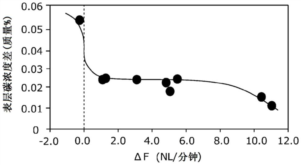
[0210] Hereinafter, the effects of the vacuum carburizing treatment method according to the present embodiment will be described more specifically using examples. The conditions in the following examples are an example of conditions employed to confirm the feasibility and effect of the vacuum carburizing treatment method of this embodiment. Therefore, the vacuum carburizing treatment method of this embodiment is not limited to this one example of conditions.

[0211] A steel pipe for machine structural use (hereinafter referred to as steel pipe) having a chemical composition corresponding to SCM415 specified in JIS G 4053 (2008) and a round bar corresponding to SCM415 were prepared. The C content of the steel pipes and round bars of each test number was 0.15% by mass. The diameter of the steel pipe is 34mm, the wall thickness is 4.5mm, and the length is 110mm. The round bar has a diameter of 26 mm and a length of 70 mm. The evaluation of the vacuum carburizing treatment was...


PUM

PropertyMeasurementUnit
sizeaaaaaaaaaa
diameteraaaaaaaaaa
thicknessaaaaaaaaaa

Abstract

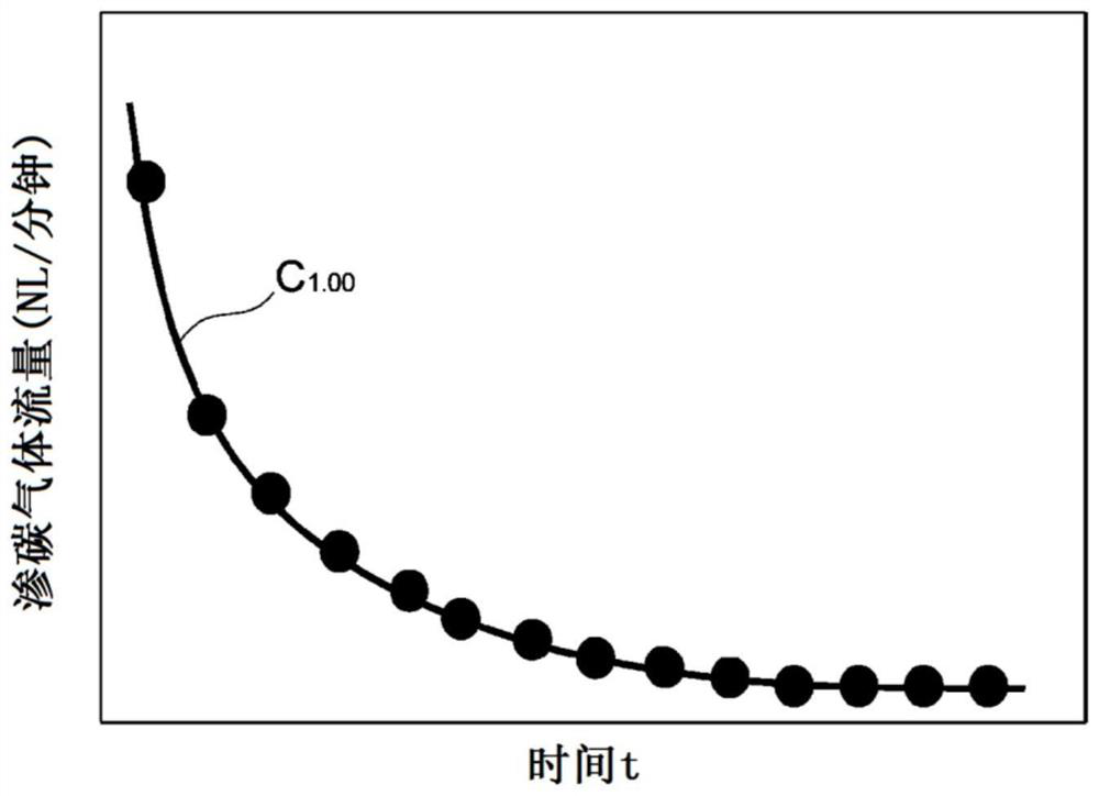
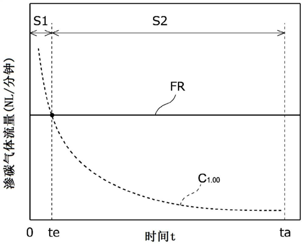
In the vacuum carburizing treatment method according to this embodiment, the flow rate of carburizing gas calculated from the diffusion flux of carbon in the surface layer of the steel material obtained from the diffusion simulation using the diffusion equation is defined as the theoretical carburizing gas flow rate (FT) , the moment when the actual carburizing gas flow rate is equal to the theoretical carburizing gas flow rate after the carburizing process starts is defined as the intersection time te, and the time from the beginning to the end of the carburizing process is defined as the carburizing time ta, and the carburizing process is defined as The time of 1 / 5 of the time is defined as the reference time ta / 5. At this time, in the early carburizing process (S1) from the start of the carburizing process to the intersection time te, the actual carburizing gas flow rate (FR) It is: the theoretical carburizing gas flow rate (FT(te)) above the reference time ta / 5 from the start of the carburizing process, and the theoretical carburizing gas flow rate (FT(20s) at 20 seconds from the start of the carburizing process )) or less; in the late carburizing process (S2) from the intersection time te to the carburizing time ta, the actual carburizing gas flow rate (FR) is 1.00 to 1.20 times the theoretical carburizing gas flow rate (FT) within range.

Description

technical field [0001] The present application relates to a vacuum carburizing treatment method and a method of manufacturing a carburized part. Background technique [0002] Steel parts for which high surface fatigue strength is required are manufactured by subjecting steel materials to surface hardening treatment. One of the surface hardening treatment methods is a vacuum carburizing treatment method. The vacuum carburizing treatment method includes a carburizing step and a diffusion step. In the carburizing step, a carburizing gas that is a hydrocarbon gas is introduced to increase the carbon concentration on the surface of the steel material heated to the carburizing temperature. The hydrocarbon gas is, for example, acetylene, propane, or the like. In the diffusion step, after the carburizing step, the introduction of the carburizing gas is stopped, and carbon is diffused in the depth direction of the surface layer of the steel material. By adjusting the time of the ...

Claims


Application Information

Patent Timeline
Patent Type & Authority Patents(China)
IPC IPC(8): C23C8/22
CPCC23C8/22
Inventor 藤堂尚二中谷贵行今高秀树
Owner NIPPON STEEL CORP
Learn More