
Discharging lifting cylinder lower limit detection device for lifting loading

A detection device, lifting drum technology, applied in the direction of measuring device, loading/unloading, utilization of re-radiation, etc., can solve the problem of placing it on the lower cargo box or cargo, the steel rope is detached from the reel, the lifting drum is stuck and is pulled by the car, etc. problem, to achieve the effect of preventing the copper rope from falling out of the groove

Pending Publication Date: 2020-11-03
仁寿县汪洋建宝水泥有限公司
View PDF7 Cites 0 Cited by
  • Summary
  • Abstract
  • Description
  • Claims
  • Application Information

AI Technical Summary

Problems solved by technology

[0002] In the existing life, in the lifting loading system that uses steel ropes for traction, due to the inconsistent height of the container of the loaded vehicle, or the change in the stacking height of the goods during the loading process, the lifting cylinder in the traditional loading system The lower limit position is fixed, and it often happens that the lifting cylinder is actually placed on the lower container or goods, but the fixed lower limit switch has not yet moved, causing the steel rope to break away from the reel, and the feeding lifting cylinder is stuck and damaged by the car. situation occurs

Method used


Image

  • Discharging lifting cylinder lower limit detection device for lifting loading
  • Discharging lifting cylinder lower limit detection device for lifting loading
  • Discharging lifting cylinder lower limit detection device for lifting loading

Examples


Embodiment

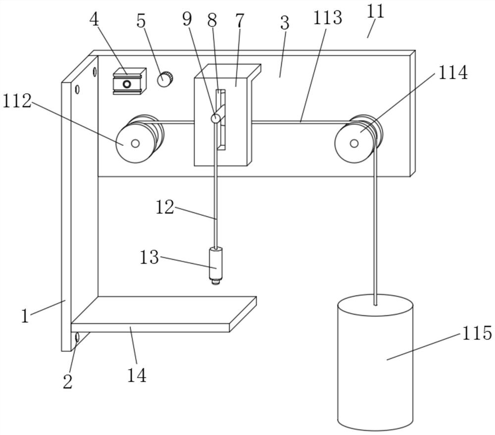
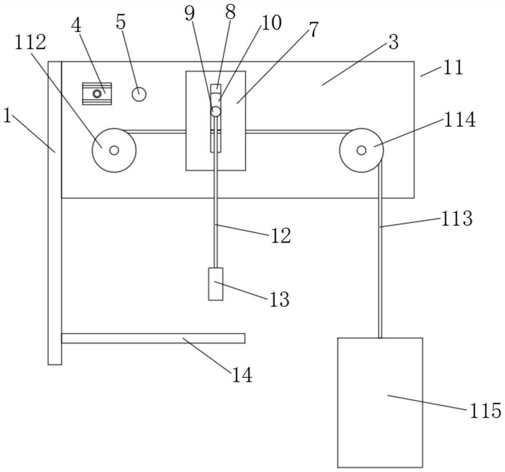
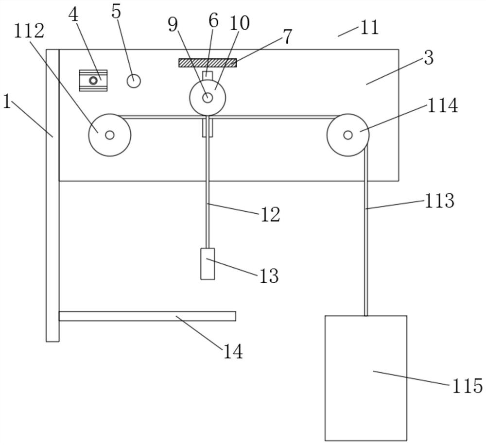
[0023] A device for detecting the lower limit of the blanking and lifting cylinder for lifting and loading vehicles, comprising a mounting plate 1, one side of the top of the mounting plate 1 is fixedly connected with a fixing plate 3, and the outer side of the fixing plate 3 is fixed and installed close to one end of the mounting plate 1 There is a processor 4, the middle part of the fixed plate 3 is provided with a first chute 6, and the outside of the fixed plate 3 is fixedly connected with a connecting plate 7 with an L-shaped structure above the first chute 6. A side of the plate 7 far away from the fixed plate 3 is provided with a second chute 8, and a slide bar 9 is slidably connected between the first chute 6 and the second chute 8, and the outside of the slide bar 9 is located on the fixed side. A detection pulley 10 is fixedly connected between the plate 3 and the connection plate 7, and a lifting mechanism 11 is arranged on the outside of the fixed plate 3 and below ...


PUM


Abstract

The invention discloses a discharging lifting cylinder lower limit detection device for lifting loading. The discharging lifting cylinder lower limit detection device for lifting loading comprises a mounting plate, a fixing plate is fixedly connected to one side of the top of the mounting plate, a processor is fixedly mounted at the end, close to the mounting plate, of the outer side of the fixingplate, and a first sliding groove is formed in the middle of the fixing plate; and a connecting plate of an L-shaped structure is fixedly connected to the position, located above the first sliding groove, of the outer portion of the fixing plate, and a second sliding groove is formed in the side, away from the fixing plate, of the connecting plate. According to the discharging lifting cylinder lower limit detection device for lifting loading, when a lifting cylinder descends to a supporting object below, it is timely detected that a detecting pulley moves, then a lower limit signal is emittedto warn surrounding workers, and a winding wheel is controlled to stop rotating; meanwhile, the device does not have a fixed lower limit and is not affected by the loading height of a vehicle, and asignal is sent to stop descending as long as the loading lifting cylinder is subjected to the supporting effect below, so that the situations that a copper rope is disengaged from a groove and a lifter is pulled to be damaged can be thoroughly prevented, and an automatic and dynamic lower limit detection signal is realized.

Description

technical field [0001] The invention belongs to the field of detection devices, in particular to a detection device for the lower limit of a blanking lifting cylinder for lifting and loading vehicles. Background technique [0002] In the existing life, in the lifting loading system that uses steel ropes for traction, due to the inconsistent height of the container of the loaded vehicle, or the change of the stacking height of the goods during the loading process, the lifting cylinder in the traditional loading system The lower limit position is fixed, and it often happens that the lifting cylinder is actually placed on the lower container or goods, but the fixed lower limit switch has not yet moved, causing the steel rope to detach from the reel, and the feeding lifting cylinder is stuck and damaged by the car. situation occurs. Invention content: [0003] The object of the present invention is to provide a lower limit detection device for the unloading cylinder for lifti...

Claims


Application Information

Patent Timeline
Patent Type & Authority Applications(China)
IPC IPC(8): B65G67/04G01S17/08
CPCB65G67/04G01S17/08
Inventor 寇永强海涛张程胡常生范天才
Owner 仁寿县汪洋建宝水泥有限公司
Learn More