Excavator electronic enclosure wall configuration method, excavator controller and excavator
An excavator controller, electronic fence technology, applied in the direction of earthmoving machine/shovel, construction, etc., can solve the problems of affecting work efficiency, under-protection of electronic fence, excessive rotation stop advance, etc., and achieve a large working range , the effect of improving work efficiency
- Summary
- Abstract
- Description
- Claims
- Application Information
AI Technical Summary
Problems solved by technology
Method used
Image

Examples
Embodiment 1
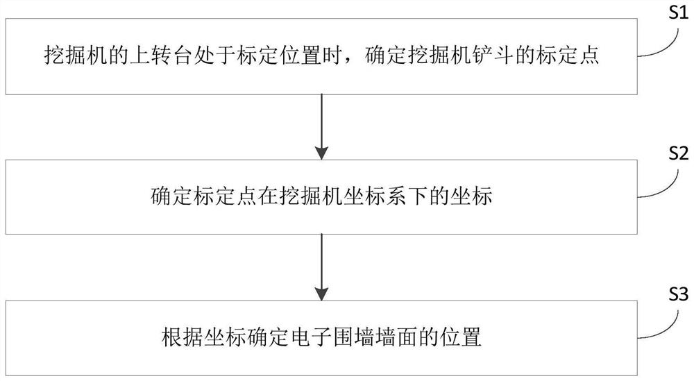
[0044] figure 2 It is the flow chart of the electronic fence configuration method in the embodiment. This embodiment is applicable to the situation of configuring the electronic fence of the excavator. The method can be executed by the excavator controller. Refer to figure 2 , the excavator electronic fence configuration methods include:
[0045] S1. When the upper turntable of the excavator is at the calibration position, determine the calibration point of the bucket of the excavator.
[0046] In this embodiment, before the actual excavation work is performed, a bucket is used to determine the range covered by the electronic fence. In this embodiment, the calibration position is the limit position to which the bucket can move when determining the electronic fence, and there may be one or more calibration positions. The calibration point can be the corner points on the left and right sides of the front end of the bucket, or the midpoint of the front end of the bucket.
[...
Embodiment 2
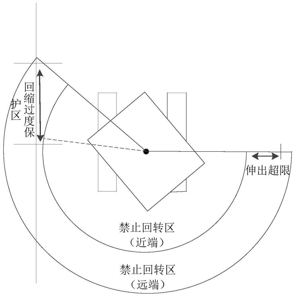
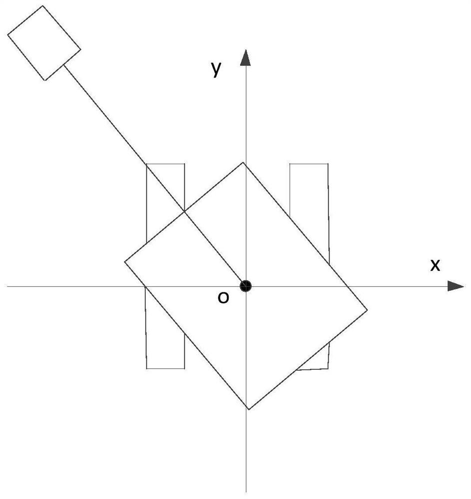
[0055] Figure 4 It is a schematic diagram of an electronic fence in the embodiment, refer to Figure 4 , as an alternative, in this embodiment, when the upper turntable of the excavator is at the calibration position, determine the vertical distance between the calibration point and the axis of the lower turntable, as the abscissa of the coordinate, determine that it is parallel to the axis and the distance is the same as the abscissa The same plane area, configure the plane area as the wall of the electronic fence located on one side or both sides of the excavator.
[0056] Exemplarily, if an obstacle (such as a wall of a building) is located on one side of the excavator within the working range of the excavator, the position of the electronic fence can be determined only by one calibration position, for example, the obstacle Taking the object as a wall as an example, the configuration process of the electronic fence includes:
[0057] Step 1. Adjust the position of the ex...
Embodiment 3
[0078] Figure 5 is another schematic diagram of electronic fence in the embodiment, refer to Figure 5 , as an optional solution, in this embodiment, the position of the electronic fence wall on this side of the excavator is determined by using two calibration positions on one side of the excavator.
[0079] Exemplarily, the configuration process of the electronic fence includes:
[0080] Step 1. Adjust the attitude of the excavator arm, boom and bucket so that the bucket extends to the farthest position relative to the main body of the excavator.
[0081] Step 2. Control the upper turntable of the excavator to rotate to one side of the obstacle until the end of the bucket is close to the obstacle.
[0082] Exemplarily, in this step, if the upper turntable rotates to the right, the right corner point at the front end of the bucket is the calibration point, and the position when the upper turntable stops rotating is the first calibration position; if the upper turntable rota...
PUM
 Abstract
Description
Claims
Application Information
 - R&D Engineer
- R&D Manager
- IP Professional
- Industry Leading Data Capabilities
- Powerful AI technology
- Patent DNA Extraction
Browse by: Latest US Patents, China's latest patents, Technical Efficacy Thesaurus, Application Domain, Technology Topic.
© 2024 PatSnap. All rights reserved.Legal|Privacy policy|Modern Slavery Act Transparency Statement|Sitemap