Student desk and chair convenient to carry and place
A technology for desks and chairs and students, which is applied in the field of desks and chairs for students, can solve problems such as inconvenient transportation, and achieve the effect of saving manpower
- Summary
- Abstract
- Description
- Claims
- Application Information
AI Technical Summary
Problems solved by technology
Method used
Image

Examples
Embodiment 1
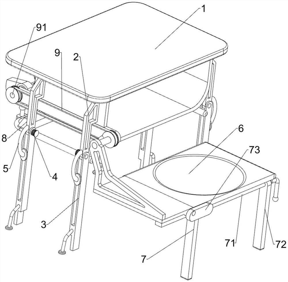
[0025] A kind of student desk and chair that is convenient to carry, such as Figure 1-3 As shown, it includes a table body 1, a first fixed rod 2, a pole 3, a torsion spring 4 and a second fixed rod 5, and the front and rear sides of the table body 1 are connected with two first fixed rods 2, and the first fixed rod 2 is hingedly connected with support rods 3, and the support rods 3 on both sides are arranged in a staggered manner. A torsion spring 4 is connected between the support rods 3 and the first fixed rod 2, and a second fixed rod 5 is connected to the first fixed rod 2. The second fixed rod 5 is used to resist the pole 3, and also includes a cushion assembly 6, a support assembly 7 and a lifting assembly 8, the table body 1 is provided with a cushion assembly 6 and a lifting assembly 8, and the cushion assembly 6 is provided with a support assembly 7.
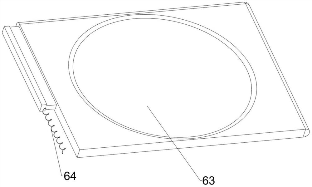
[0026] Cushion assembly 6 comprises limit rod 61, swing frame 62, seat plate 63 and elastic member 64, and table b...
Embodiment 2
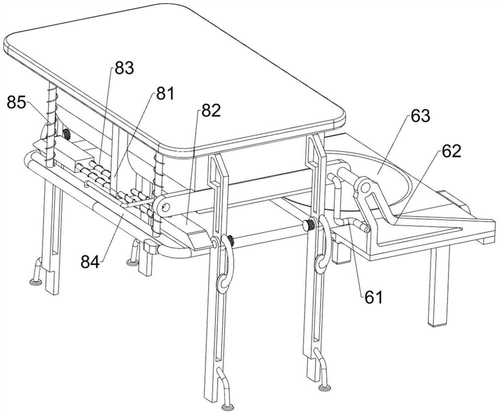
[0031] On the basis of Example 1, such as Figure 4 As shown, the extruding assembly 9 is also included. The extruding assembly 9 includes a first rotating shaft 91, a first one-way clutch 92, a cam 93 and a connecting rod 94. The left side of the table body 1 is connected to the first rotating shaft 91 in a rotational manner. The first rotating shaft 91 is connected with a first one-way clutch 92, the first one-way clutch 92 is connected with a cam 93, the first rotating shaft 91 is connected with the transmission shaft of the swing frame 62, and the sliding rod 84 is connected with a connecting rod 94, The connecting rod 94 cooperates with the cam 93 .
[0032] When the swing frame 62 rotates, it drives the first rotating shaft 91 to rotate. At this time, under the action of the first one-way clutch 92, the rotation of the first rotating shaft 91 will not drive the rotation of the cam 93. The swing frame 62 also drives the first rotating shaft when it rotates in the reverse ...
Embodiment 3
[0034] On the basis of Example 2, such as Figure 4As shown, a pulling assembly 10 is also included, and the pulling assembly 10 includes an extension rod 101, a straight rack 102, a second rotating shaft 103, a second one-way clutch 104, a bevel gear 105 and a tooth-missing gear 106, and two wedge blocks 82 Both are connected with an extension rod 101, the extension rod 101 is connected with a straight rack 102, the left side of the table body 1 is connected with a second rotating shaft 103, and the second rotating shaft 103 is connected with a second one-way clutch 104. A bevel gear 105 is connected to the clutch 104 and the first rotating shaft 91, and the two bevel gears 105 mesh with each other. The bottom of the second rotating shaft 103 is connected with a toothless gear 106, and the toothless gear 106 meshes with the spur rack 102.
[0035] When the first rotating shaft 91 rotates, the bevel gear 105 drives the second rotating shaft 103 to rotate, and the rotation of t...
PUM
 Abstract
Description
Claims
Application Information
 - R&D Engineer
- R&D Manager
- IP Professional
- Industry Leading Data Capabilities
- Powerful AI technology
- Patent DNA Extraction
Browse by: Latest US Patents, China's latest patents, Technical Efficacy Thesaurus, Application Domain, Technology Topic.
© 2024 PatSnap. All rights reserved.Legal|Privacy policy|Modern Slavery Act Transparency Statement|Sitemap