
Patient diet heat preservation cabinet for digestive system department

A technology for gastroenterology and heat preservation cabinets, which is applied to trolley accessories, motor vehicles, trolleys, etc., can solve problems such as inconvenience of movement, and achieve the effect of saving manpower

Active Publication Date: 2021-07-30
滨州医学院附属医院
View PDF14 Cites 0 Cited by
  • Summary
  • Abstract
  • Description
  • Claims
  • Application Information

AI Technical Summary

Problems solved by technology

[0005] In order to overcome the disadvantage that the above-mentioned patent insulation cabinet is not equipped with a moving part, which is inconvenient when moving, the technical problem to be solved by the invention is to provide a moving part, which makes it more convenient to manually move the insulation cabinet. Diet warmer for patients in gastroenterology

Method used


Image

  • Patient diet heat preservation cabinet for digestive system department
  • Patient diet heat preservation cabinet for digestive system department
  • Patient diet heat preservation cabinet for digestive system department

Examples


Embodiment 1

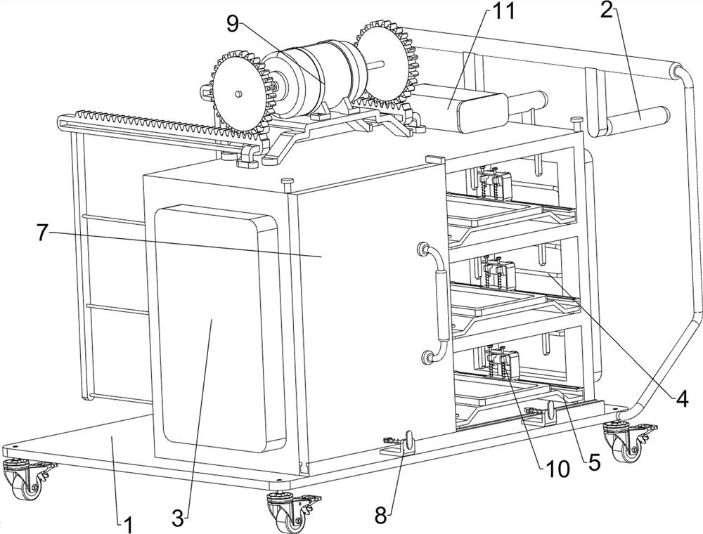
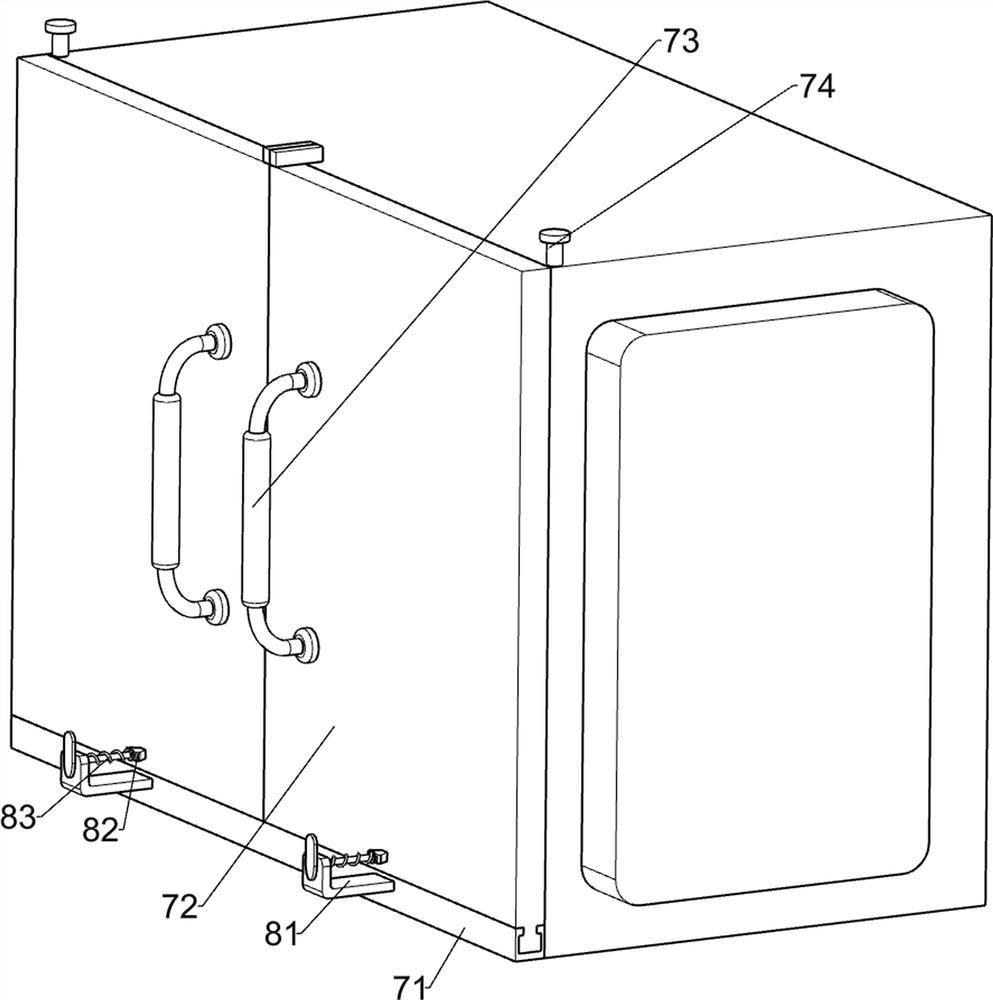
[0030] A patient's diet warming cabinet for gastroenterology, such as Figure 1-3 As shown, it includes a cart 1, a first handle 2, an insulated cabinet 3, a heating wire 4 and a tray 5, the right side of the cart 1 is connected with the first handle 2, and the top of the cart 1 is connected with the insulated cabinet 3. A plurality of heating wires 4 are installed on the left and right side walls of the cabinet 3, and multiple trays 5 are slidingly connected to the left and right sides of the insulation cabinet 3 at even intervals, and also include an opening and closing mechanism 7 and a locking mechanism 8. 3 is provided with an opening and closing mechanism 7, and the opening and closing mechanism 7 is provided with a locking mechanism 8.

[0031] The opening and closing mechanism 7 includes a guide carriage 71, a straight baffle plate 72, a second handle 73 and a stop bar 74. The lower part of the front side of the insulation cabinet 3 is connected with a guide carriage 7...

Embodiment 2

[0036] On the basis of Example 1, such as Figure 4 As shown, ejection mechanism 9 is also included, and ejection mechanism 9 includes fixed frame 91, low-speed motor 92, rotating shaft 93, spur gear 94, guide slider 95, rack 96 and ejector rod 97, and the top of insulation cabinet 3 is connected Fixed frame 91 is arranged, and low-speed motor 92 is installed on the fixed frame 91, and low-speed motor 92 is biaxial setting, and rotating shaft 93 is all connected on the two output shafts of low-speed motor 92, is connected with spur gear 94 on the rotating shaft 93, insulation cabinet 3 The left and right sides of the top are connected with guide sliders 95, the guide slider 95 is slidably connected with a rack 96, the rack 96 meshes with the spur gear 94, and the rack 96 is connected with a plurality of push rods 97 evenly spaced. 97 is slidingly matched with insulation cabinet 3, and push rod 97 is connected with tray 5.

[0037]When needs will be pulled out, can start low-s...

Embodiment 3

[0041] On the basis of Example 2, such as Figure 4 and Figure 7 As shown, a storage mechanism 11 is also included, and the storage mechanism 11 includes a top block 1101, a storage rack 1102, a storage box 1103 and a third spring 1104, and the rack 96 on the right is connected with a top block 1101 for heat preservation. A storage rack 1102 is connected to the right side of the top of the cabinet 3, a storage box 1103 is slidably connected in the storage rack 1102, a third spring 1104 is connected between the storage box 1103 and the storage rack 1102, and the top block 1101 is connected to the storage rack 1102. Box 1103 fits.

[0042] When placing the tableware, the tableware can be placed in the storage box 1103, the rack 96 can drive the top block 1101 to move forward when moving forward, and when the top block 1101 moves forward to contact with the storage box 1103, the top block 1101 The block 1101 continues to move forward to push the storage box 1103 to move forwar...


PUM


Abstract

The invention relates to a heat preservation cabinet and particularly relates to a patient diet heat preservation cabinet for the digestive system department. The technical problem to be solved by the invention is how to design the patient diet heat preservation cabinet for the digestive system department, which is provided with a moving part and is more convenient to move manually. In order to solve the technical problem, the patient diet heat preservation cabinet for the digestive system department comprises a cart, a heat preservation cabinet, electric heating wires, trays, an opening and closing mechanism and a clamping mechanism, wherein one side of the cart is connected with a first grip; the top of the trolley is connected with the heat preservation cabinet; the two side walls in the heat preservation cabinet are each provided with the multiple electric heating wires; a plurality of trays are uniformly connected to the two sides in the heat preservation cabinet at intervals in a sliding manner; the opening and closing mechanismis arranged on the heat preservation cabinet; and the clamping mechanism is arranged on the opening and closing mechanism. The cabinet is advantaged in that basic functions of the heat preservation cabinet are achieved through cooperative operation of the opening and closing mechanism, the clamping mechanism, the heat preservation cabinet and the electric heating wire.

Description

technical field [0001] The invention relates to a warming cabinet, in particular to a patient's diet warming cabinet for gastroenterology. Background technique [0002] Gastroenterology is a third-level clinical discipline that mainly studies diseases of the esophagus, stomach, small intestine, large intestine, liver, gallbladder, and pancreas. Gastroenterology has a wide variety of diseases, a wide range of medical knowledge, and complex and delicate operations. There is usually particular attention to food, and it is usually necessary to store it in a warm cabinet when storing food for gastroenterology patients. [0003] After retrieval, the authorized patent publication number is CN207544957U, which discloses a heat preservation cabinet, including a cabinet body and an operation table, the bottom end of the operation table is fixedly connected to the top of the cabinet body, and the upper end surface of the operation table is provided with Storage trough, several basins ...

Claims


Application Information

Patent Timeline
IPC IPC(8): A47J39/02B62B5/04
CPCA47J39/02B62B5/0438B62B5/0476
Inventor 兰晓红
Owner 滨州医学院附属医院
Learn More