Field portable surveying and mapping tool storage device
A tool storage and portable technology is applied in the field of field portable surveying and mapping tool storage devices, which can solve the problems of inconvenient storage and insufficient portability, and achieve the effect of being convenient to carry.
- Summary
- Abstract
- Description
- Claims
- Application Information
AI Technical Summary
Problems solved by technology
Method used
Image
Examples
Embodiment 1
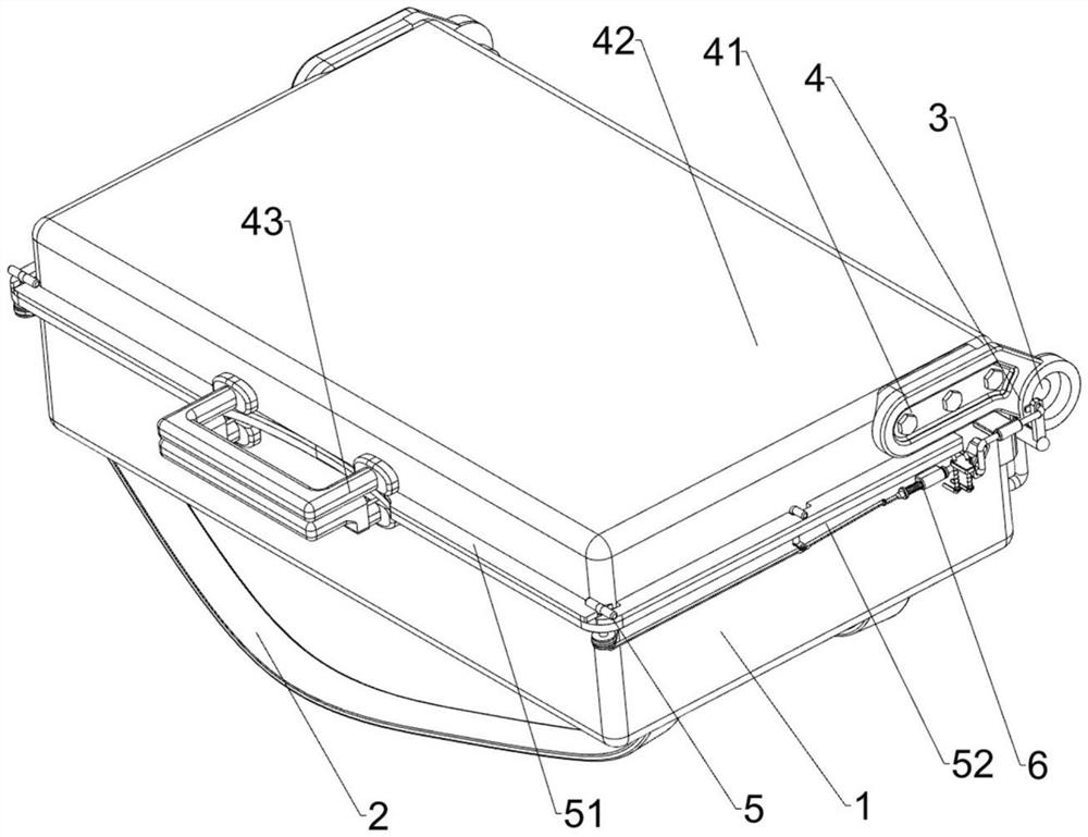
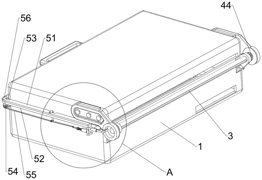
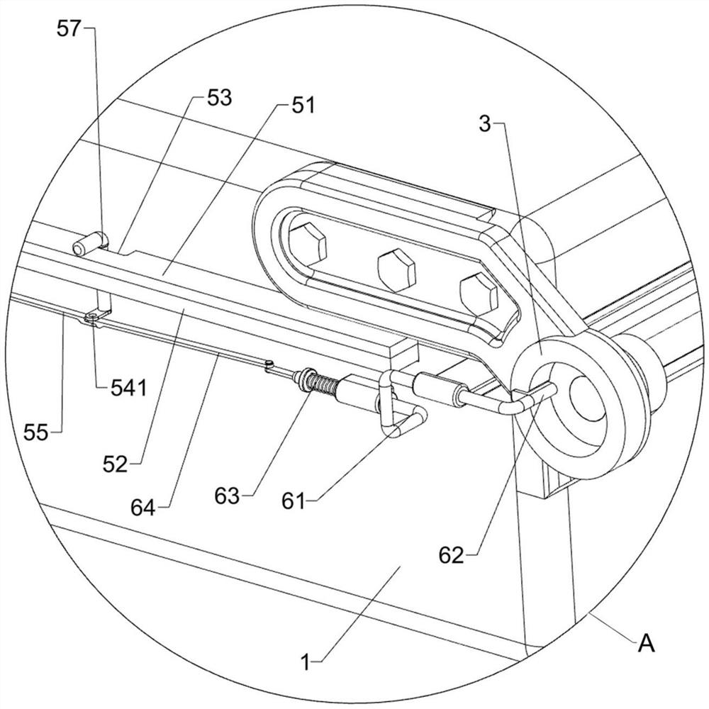
[0031] A field portable surveying and mapping tool storage device, such as Figure 1 to Figure 7 As shown, it includes a box body 1, a strap 2 and a sheave 3. Two straps 2 are connected to the bottom of the box body 1. The left and right sides of the box body 1 are rotatably connected to a sheave 3. The two sheaves 3 are coaxial. Setting also includes cover assembly 4, buckle assembly 5, slide assembly 6, placement assembly 7 and spacer assembly 8, sheave 3 is provided with cover assembly 4 and spacer assembly 8, cover assembly 4 and box A buckle assembly 5 is provided between the bodies 1 , and a sliding assembly 6 and a placement assembly 7 are provided on the box body 1 .
[0032] Cover assembly 4 includes connecting frame 41, closing frame 42, handle 43, torsion spring 44 and storage net bag 45, is connected with connecting frame 41 on the sheave 3, is connected with closing frame 42 between two connecting frames 41, closes A handle 43 is connected to the frame 42 and the...
Embodiment 2
[0039] On the basis of Example 1, such as Figure 5 , Figure 7 and Figure 8 Shown, also include extruding assembly 9, extruding assembly 9 includes air bag 91, second slide frame 92, push plate 93, slider 94, cylinder 95, piston 96, push frame 97 and connecting pipe 98, box Two airbags 91 are connected in the body 1, a second sliding frame 92 is connected on the sliding sleeve 81, a push plate 93 is connected on the second sliding frame 92, a slider 94 is slidably connected to the lower part of the rear side of the box body 1, and the push plate 93 cooperates with slide block 94, and cylinder body 95 is installed on the bottom of fixed plate 71, and piston 96 is slidably connected in cylinder body 95, and is connected with push frame 97 on piston 96, and push frame 97 is slidingly matched with cylinder body 95, and push frame 97 Connected with the slider 94 , the air outlet end of the cylinder body 95 is connected with a communication pipe 98 , and the communication pipe 9...
Embodiment 3
[0042] On the basis of Example 2, such as Figure 6 As shown, it also includes a limit assembly 10. The limit assembly 10 includes a guide rail 101, a sliding block 102, a return spring 103, and an extrusion frame 104. The block 102 , the return spring 103 is connected between the sliding block 102 and the guide rail 101 , and the extruding frame 104 is connected on the sliding block 102 , and the extruding frame 104 cooperates with the first sliding frame 61 .
[0043] When it is necessary to pull the clamping block 62 to move backward, the sliding block 102 can be pulled to move downward, and the return spring 103 is compressed, and the downward movement of the sliding block 102 drives the extrusion frame 104 to move downward. When the extrusion frame 104 moves downward The first sliding frame 61 can be used to push the block 62 to move backward. When a person accidentally bumps into the first locking bar 56 and the second locking bar 57, the extrusion frame 104 can be again...
PUM
 Abstract
Description
Claims
Application Information
 - R&D
- Intellectual Property
- Life Sciences
- Materials
- Tech Scout
- Unparalleled Data Quality
- Higher Quality Content
- 60% Fewer Hallucinations
Browse by: Latest US Patents, China's latest patents, Technical Efficacy Thesaurus, Application Domain, Technology Topic, Popular Technical Reports.
© 2025 PatSnap. All rights reserved.Legal|Privacy policy|Modern Slavery Act Transparency Statement|Sitemap|About US| Contact US: help@patsnap.com


