Torsion unloading mechanism

A technology of torsion and circular sleeves, applied in metal processing, metal processing equipment, manufacturing tools, etc., can solve problems such as unloading of bolts and nuts, and achieve the effect of ensuring normal use

Active Publication Date: 2020-11-06
SHANGHAI UNIVERSITY OF ELECTRIC POWER
View PDF7 Cites 0 Cited by
  • Summary
  • Abstract
  • Description
  • Claims
  • Application Information

AI Technical Summary

Problems solved by technology

[0005] In view of the problem that the above-mentioned existing torsion unloading mechanism cannot unload two or more bolt and nut combinations at the same time, the present invention is proposed

Method used


Image

  • Torsion unloading mechanism
  • Torsion unloading mechanism
  • Torsion unloading mechanism

Examples


Embodiment 1

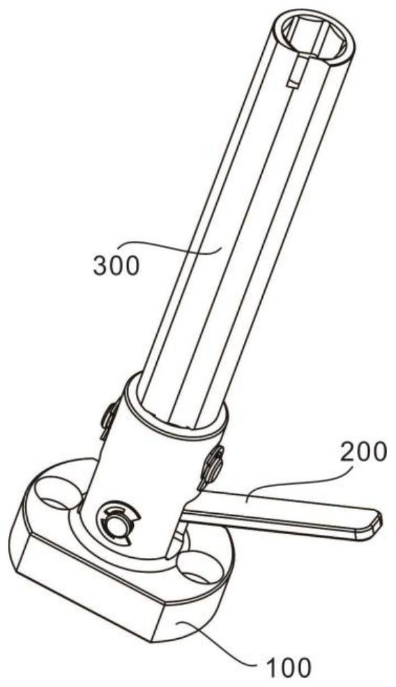
[0030] refer to Figure 1-6 , provides a schematic diagram of the overall structure of a torsion unloading mechanism, such as figure 1 , a torsional unloading mechanism includes a bearing unit 100 for carrying components, a base 101 for carrying components, a first circular sleeve 102 for accommodating and limiting the adjustment unit 200 , a seat for accommodating the adjustment unit 200 The inner space N1, the adjusting unit 200 for adjusting the mechanism, the roller 201 for rotating the adjusting unit 200, the first pin 202 for limiting the roller 201, the unloading unit 300 for unloading the torque, and the following roller 201 The upright column 301, which moves up and down, solves the problem that two or more bolt and nut combinations cannot be unloaded at the same time through the mutual cooperation between the adjustment unit and the unloading unit. The load-bearing unit provides stable working conditions for the mechanism. Ensure the normal use of the institution. ...

Embodiment 2

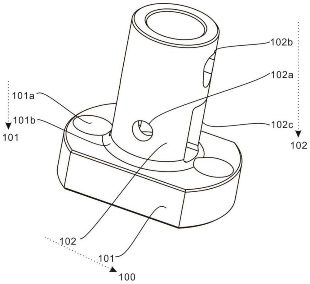
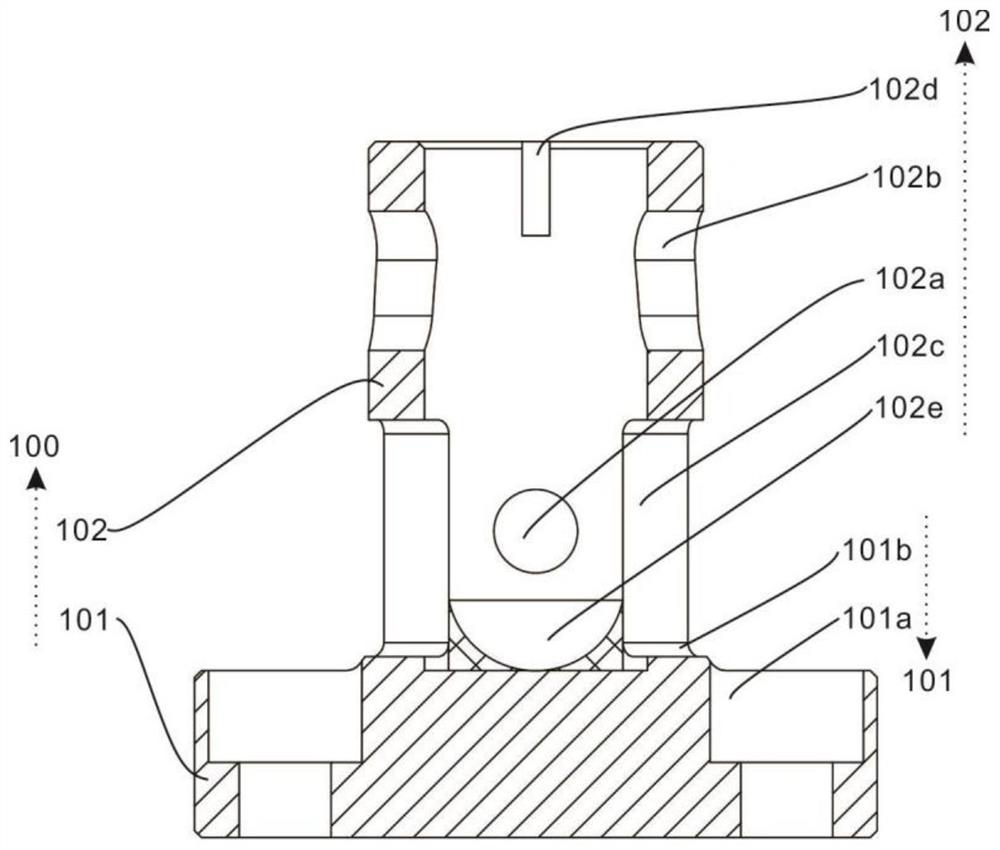
[0034] refer to Figure 2-5 , this embodiment is different from the first embodiment in that: the bearing unit 100 for carrying the components also includes a limiting hole 101a that cooperates with screws to limit the base 101, and a hole 101a that fixes the first circular sleeve 102. The fixing ring 101b, the through hole 102a for limiting the adjustment unit 200, the inverted triangular groove 102b for limiting the unloading unit 300, the square groove 102c for allowing the adjustment unit 200 to rotate, and the position limiting for the unloading unit 300 The limit groove 102d, the first limit block 102e for limiting the roller 201, the limit hole 101a cooperates with the screw to fix the base 101, and the fixing ring 101b fixes the first circular sleeve 102, thereby ensuring the device normal use.

[0035]Specifically, the two sides of the base 101 that carries the components are provided with limiting holes 101a that cooperate with screws to limit the base 101, and the ...

Embodiment 3

[0039] refer to Figure 2-5 , this embodiment is different from the above embodiments in that: the adjustment unit 200 for adjusting the mechanism also includes a pressing rod 203 for driving the roller 201 to rotate and a first limit ring 202a for limiting the first pin 202, through Press the pressing rod 203 to drive the roller 201 to rotate with the first pin 202 as the axis of rotation, so that the roller 201 is displaced upward while rotating with the first pin 202 as the axis of rotation, thereby driving the unloading unit 300 to be displaced upward , the first limit ring 202a limits the first pin 202, thereby ensuring that the adjustment unit 200 can operate normally.

[0040] Specifically, the adjustment unit 200 for adjusting the mechanism also includes a pressure rod 203 that drives the roller 201 to rotate. The pressure rod 203 is fixedly connected to the outside of the roller 201. The pressure rod 203 passes through the square groove 102c and extends to the outside...


PUM


Abstract

The invention discloses a torsion unloading mechanism. The torsion unloading mechanism comprises a bearing unit, an adjusting unit and an unloading unit; the bearing unit comprises a base and a firstcircular sleeve fixed to the center of the top of the base; the adjusting unit comprises a roller and a first pin rod penetrating through the roller, and the roller is located in the inner space of the first circular sleeve; and the unloading unit comprises a stand column, and the bottom end of the stand column is located in the inner space of the first circular sleeve. According to the torsion unloading mechanism, the bearing unit, the adjusting unit and the unloading unit are arranged, the problem that two or more bolt and nut combinations cannot be unloaded at the same time is solved through mutual cooperation of the adjusting unit and the unloading unit, the bearing unit provides stable working conditions for the mechanism, and normal use of the mechanism is guaranteed.

Description

technical field [0001] The invention relates to the technical field of torsion unloading tools, in particular to a torsion unloading mechanism. Background technique [0002] In recent years, as more and more traditional production and assembly lines have begun to develop in the direction of intelligence and unmanned, the engine industry of small aerospace equipment such as drones has risen rapidly; compared with traditional vehicle engines, This type of small engine has a more compact structure, and the assembly space is very narrow. There are often no threaded holes in the workpiece. It is necessary to connect the two parts by screwing the bolt into the nut. In the process of screwing the bolt, the nut needs to have a counter force to Make sure the bolts are tight. [0003] When the tightening torque is small, the torque of the anti-reaction groove of the nut is relatively small, and the torque that the operator needs to overcome to take out the workpiece from the anti-rea...

Claims


Application Information

Patent Timeline
IPC IPC(8): B23P19/06
CPCB23P19/06
Inventor 刘颖慧
Owner SHANGHAI UNIVERSITY OF ELECTRIC POWER
Why Eureka
Try Eureka