
Dust removal device for carrying out wind and water combined washing on cameras under mine

A dust removal device and camera technology, applied in image communication, color TV parts, TV system parts, etc., can solve the problems of insufficient cleaning, frequent replacement, difficult cleaning, etc., to ensure normal use and low maintenance cost , to ensure the effect of clarity

Pending Publication Date: 2020-07-14
无锡华瀚能源装备科技有限公司
View PDF0 Cites 4 Cited by
  • Summary
  • Abstract
  • Description
  • Claims
  • Application Information

AI Technical Summary

Problems solved by technology

[0002] At present, the washing method of the camera of the roadheader working underground is to use the traditional cleaning cloth to wipe and clean. This cleaning method has three major disadvantages: 1. The effect of cleaning with the cleaning cloth is relatively poor: a large amount of coal will be generated underground when the roadheader is working. Dust, and in the coal dust, there will be adhesions similar to tar. This kind of adhesion is extremely difficult to clean up on the camera, so there will be dead areas when cleaning with a conventional cleaning cloth, and the cleaning is not in place; 2. It is easy to absorb Scale: After the cleaning cloth is cleaned several times, there will be coal dust attached to the cleaning cloth, which will cause scaling due to excessive accumulation of coal dust after a long time; 3. Frequent replacement: After cleaning several times, the cleaning cloth will be scaled. You need to replace the cleaning cloth, resulting in a large degree of waste of manpower and material resources
Therefore, there are high requirements for the cleanliness of the camera. The current products have the disadvantages of poor cleaning effect, easy dirt, and frequent replacement.

Method used


Image

  • Dust removal device for carrying out wind and water combined washing on cameras under mine
  • Dust removal device for carrying out wind and water combined washing on cameras under mine

Examples


Embodiment Construction

[0013] The following will clearly and completely describe the technical solutions in the embodiments of the present invention with reference to the accompanying drawings in the embodiments of the present invention. Obviously, the described embodiments are only some, not all, embodiments of the present invention. Based on the embodiments of the present invention, all other embodiments obtained by persons of ordinary skill in the art without making creative efforts belong to the protection scope of the present invention.

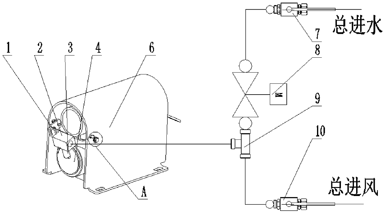
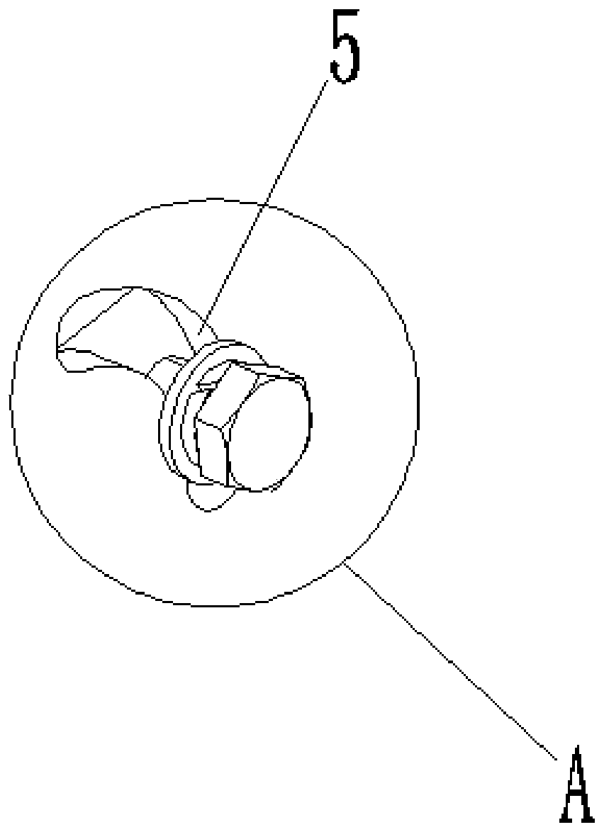
[0014] Such as Figure 1-Figure 2 As shown, this specific embodiment adopts the following technical solutions: it includes a fixed frame 1, a spray block 2, a nozzle 3, a camera 4, a U-shaped hole 5, a camera shield 6, a total water inlet 7, an electromagnetic ball valve 8, and a tee joint 9 and the total air intake 10, a camera shield 6 is installed outside the camera 4, and a fixed frame 1 is installed at the front portion of the camera shield 6, and the cam...


PUM


Abstract

The invention discloses a dust removal device for carrying out wind and water combined washing on cameras under a mine, and belongs to the technical field of heading machine camera cleaning. A cameraprotection cover is mounted on the outer portions of the cameras. A fixed frame is mounted on the front portion of the camera protection cover. U-shaped holes are formed in the two sides of the cameraprotection cover. The two ends of the fixed frame and the U-shaped holes are fixed through bolts. A mist spraying block is mounted on the fixed frame, a nozzle is mounted on the mist spraying block,and the mist spraying block is connected with a connector of a three-way joint. According to the dust removal device for carrying out wind and water combined washing on the cameras under the mine, thewind and water combined washing manner is adopted for breaking through the traditional contact type dust removal manner, the wind or water dust removal manner can be independently utilized, the mirror planes of the cameras of a heading machine re effectively cleaned, and normal use of a remote monitor of the heading machine can be ensured; the mirror planes of the cameras can be cleaned while equipment works, imaging clearness is guaranteed; and the structure is simple, mounting is convenient, and the maintenance cost is low.

Description

technical field [0001] The invention relates to a dedusting device for washing a camera head with wind and water combination under a mine, and belongs to the technical field of cleaning the camera head of a roadheader. Background technique [0002] At present, the washing method of the camera of the roadheader working underground is to use the traditional cleaning cloth to wipe and clean. This cleaning method has three major disadvantages: 1. The effect of cleaning with the cleaning cloth is relatively poor: a large amount of coal will be generated underground when the roadheader is working. Dust, and in the coal dust, there will be adhesions similar to tar. This kind of adhesion is extremely difficult to clean up on the camera, so there will be dead areas when cleaning with a conventional cleaning cloth, and the cleaning is not in place; 2. It is easy to absorb Scale: After the cleaning cloth is cleaned several times, there will be coal dust attached to the cleaning cloth, ...

Claims


Application Information

Patent Timeline
IPC IPC(8): B08B5/02B08B3/02B08B13/00H04N5/225
CPCB08B5/02B08B3/02B08B13/00H04N23/00
Inventor 丁振华刘兴利史成建王海涛孙家锐杨琳卢明亮姜光辉
Owner 无锡华瀚能源装备科技有限公司
Learn More