Display panel and display device
A technology for display panels and substrates, which can be used in instruments, optics, nonlinear optics, etc., and can solve problems such as poor display quality at wide viewing angles.
- Summary
- Abstract
- Description
- Claims
- Application Information
AI Technical Summary
Problems solved by technology
Method used
Image

Examples
Embodiment 1
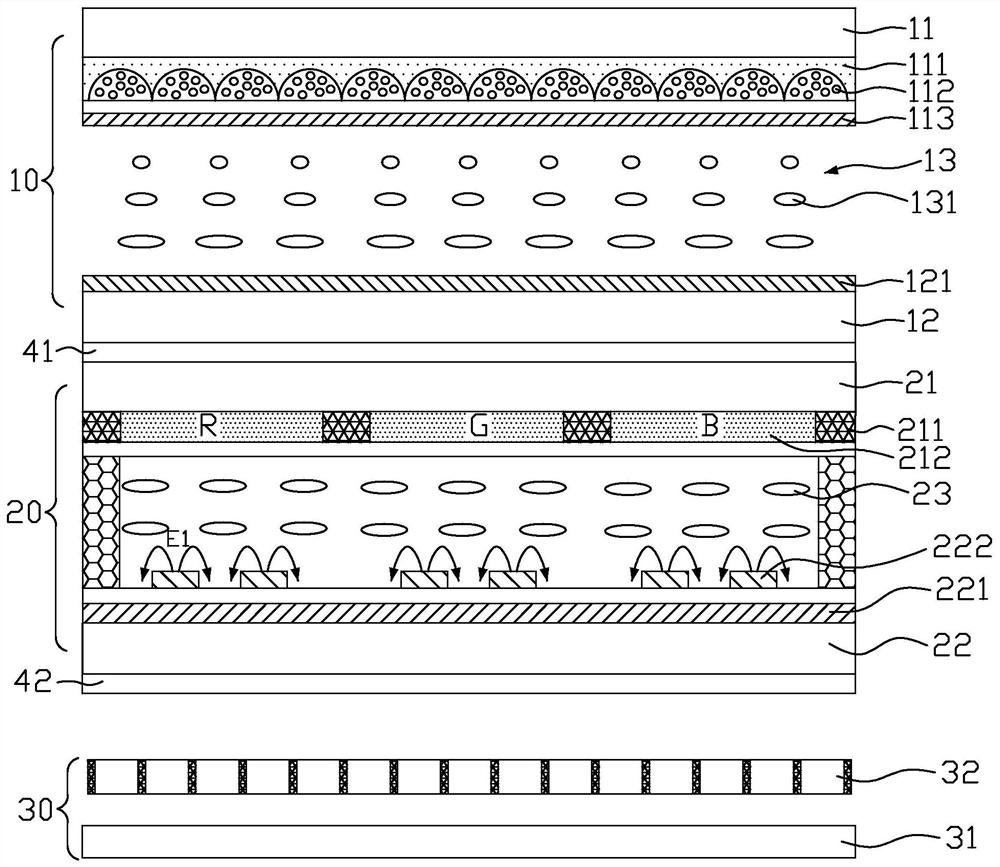
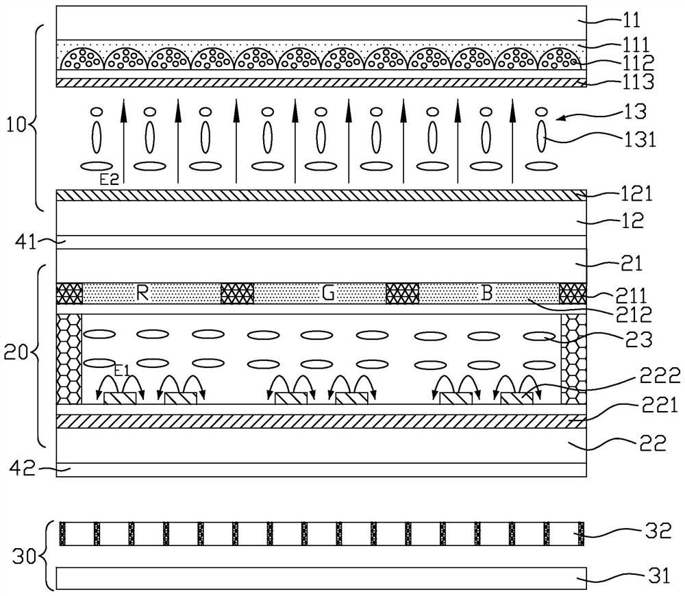
[0035] figure 1 It is a schematic structural diagram of the display device in the first embodiment of the present invention at a wide viewing angle. figure 2 It is a schematic structural diagram of the display device in Embodiment 1 of the present invention at a narrow viewing angle.
[0036] Such as figure 1 and figure 2 As shown, a display panel provided in Embodiment 1 of the present invention includes a first dimming box 10 and a display liquid crystal box 20 stacked on top of each other. On the upper side, of course, the first dimming box 10 can also be arranged on the lower side of the display liquid crystal box 20 .
[0037] Wherein, the display liquid crystal cell 20 includes a color filter substrate 21, an array substrate 22 disposed opposite to the color filter substrate 21, and a liquid crystal layer 23 located between the color filter substrate 21 and the array substrate 22. In this embodiment, the liquid crystal layer 23 adopts Positive liquid crystal molecu...
Embodiment 2
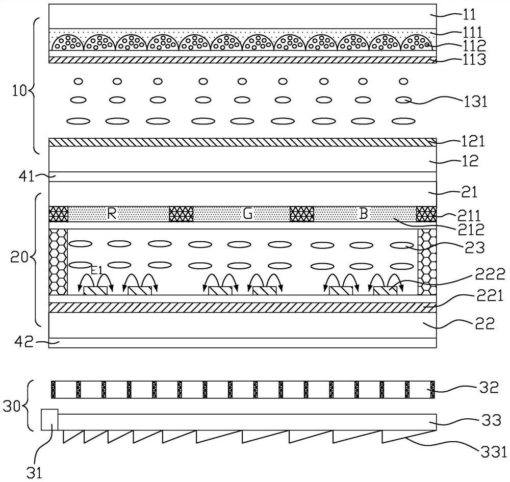
[0050] image 3 It is a schematic diagram of the structure of the display device in the second embodiment of the present invention at a wide viewing angle. The display panel provided by Embodiment 2 of the present invention is the same as Embodiment 1 ( figure 1 and figure 2 ) are basically the same display panel, the difference is that in this embodiment, the light source 31 adopts a side-type light source, the backlight module 30 also includes a light guide plate 33, the light source 31 is arranged on one side of the light guide plate 33, and the light guide plate 33 is provided with a plurality of reflective slopes 331. The reflective slopes 331 are used to reflect the light emitted by the light source 31 back in a direction perpendicular to the display surface. Different reflective slopes 331 have different slopes according to the distance from the light source 31.
[0051] Those skilled in the art should understand that the remaining structures and working principles o...
Embodiment 3
[0053] Figure 4 It is a schematic diagram of the structure of the display device in the third embodiment of the present invention at a wide viewing angle, Figure 5 yes Figure 4 Schematic diagram of the polarization direction of the selective polarizing layer in, Figure 6 It is a schematic structural diagram of the display device in the third embodiment of the present invention at a narrow viewing angle, Figure 7 yes Figure 6 Schematic illustration of the polarization directions of the middle selective polarizing layer. The display panel provided by Embodiment 2 of the present invention is the same as Embodiment 1 ( figure 1 and figure 2 ) are basically the same display panel, the difference is that in this embodiment, the second substrate 12 is provided with a second electrode 121 and a third electrode 122 in different layers, and the first selective polarizing layer 13 includes a second positive The long axes of the second positive liquid crystal molecules 132 an...
PUM
| Property | Measurement | Unit |
|---|---|---|
| refractive index | aaaaa | aaaaa |
Abstract
Description
Claims
Application Information
 - R&D Engineer
- R&D Manager
- IP Professional
- Industry Leading Data Capabilities
- Powerful AI technology
- Patent DNA Extraction
Browse by: Latest US Patents, China's latest patents, Technical Efficacy Thesaurus, Application Domain, Technology Topic.
© 2024 PatSnap. All rights reserved.Legal|Privacy policy|Modern Slavery Act Transparency Statement|Sitemap