
U-shaped belt corrugated energy dissipation part damper

A technology of dampers and waveforms, which is applied to building components, earthquake resistance, building types, etc., can solve the problems of small earthquakes that cannot produce plastic energy consumption, insufficient out-of-plane stability, and single energy consumption mechanism, achieving good economic benefits and reducing Seismic response and stable energy dissipation performance

Pending Publication Date: 2020-11-17
BEIJING UNIV OF TECH
View PDF5 Cites 0 Cited by
  • Summary
  • Abstract
  • Description
  • Claims
  • Application Information

AI Technical Summary

Problems solved by technology

[0006] The present invention proposes a U-shaped damper with wave-shaped energy-dissipating parts, which aims to solve the problem of concentrated yield points in the existing metal damper structure system, the inability to produce plastic energy consumption in small earthquakes, overall damage in large earthquakes, and the need for overall replacement after earthquakes , single energy dissipation mechanism, insufficient out-of-plane stability, etc., the new metal damper can realize a double insurance mechanism, improve structural rigidity, and has good load-bearing performance and energy dissipation performance, which can reduce the damage of the main structure; at the same time, the yield load In the case of the same force, the amount of steel used by the new damper is significantly smaller than that of the traditional U-shaped damper, which can improve economic benefits; in addition, the invention also provides more options for replaceable metal dampers

Method used


Image

  • U-shaped belt corrugated energy dissipation part damper
  • U-shaped belt corrugated energy dissipation part damper
  • U-shaped belt corrugated energy dissipation part damper

Examples


Embodiment Construction

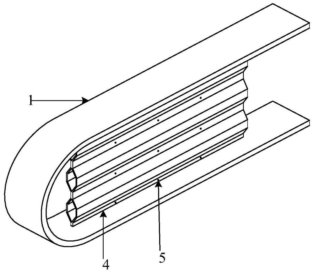
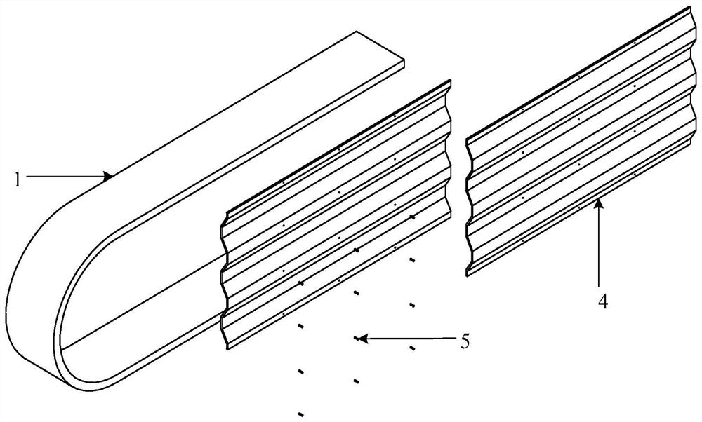
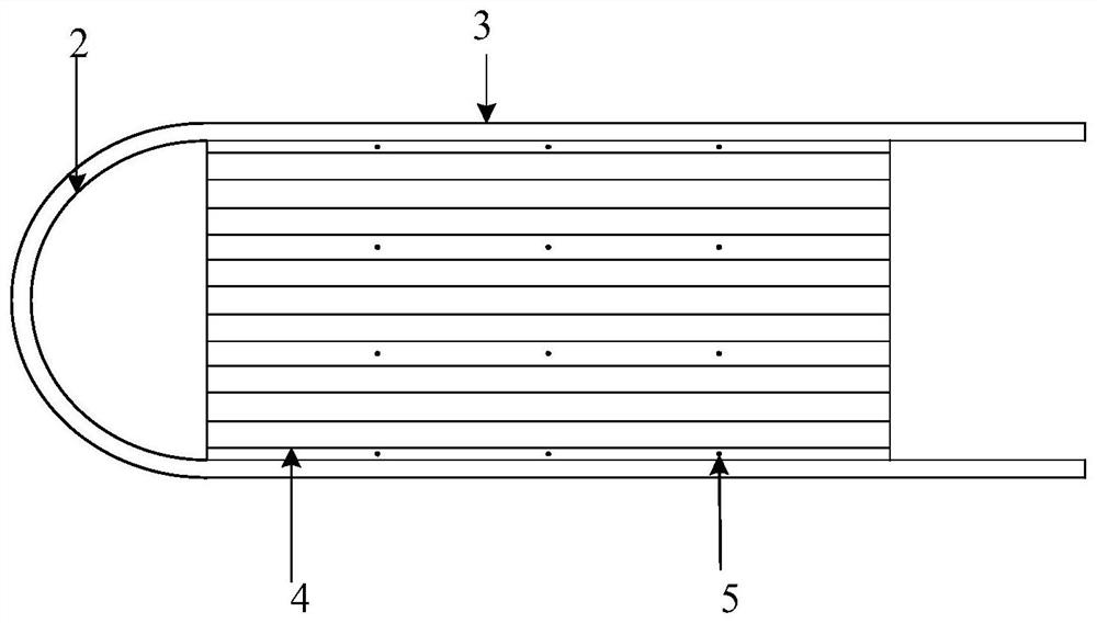
[0027] Attached below Figure 1-7 , detailing the implementation of this patent.

[0028] Such as Figure 1-7 As shown, a U-shaped damper with wave-shaped energy dissipation parts includes the following components:

[0029] 1——U-shaped energy-consuming parts;

[0030] 2 - arc segment;

[0031] 3——straight section;

[0032] 4——Double-layer waveform energy-consuming parts;

[0033] 5——Self-tapping screw;

[0034] Such as Figure 1-7 As shown, a U-shaped damper with wave-shaped energy-dissipating parts is characterized in that: the metal damper is composed of U-shaped energy-consuming parts (1) and double-layer wave-shaped energy-consuming parts (4); each U-shaped energy-dissipating part The part (1) is composed of an arc segment (2) and two straight segments (3); the double-layer wave energy dissipation part is composed of two symmetrically arranged wave energy dissipation parts, and is connected by self-tapping screws (5). Its connection; the double-layer corrugated ene...


PUM


Abstract

The invention relates to a U-shaped belt corrugated energy dissipation part damper, and belongs to the technical field of structural engineering energy dissipation and shock absorption. The damper iscomposed of a U-shaped energy dissipation part, a double-layer corrugated energy dissipation part and a plurality of self-tapping screws. The metal damper is provided on the basis of the design concepts that energy dissipation parts can be replaced, the shear bearing capacity of the damper is improved, out-of-plane buckling is restrained, the structural rigidity is improved, multiple shear energydissipation mechanisms work cooperatively, and a double-insurance mechanism is adopted, and the limitation of a traditional metal damper is broken through. Through a reasonable design, the problem that the damper is not prone to generating plastic energy dissipation and needs to consume energy of a main body structure in a small earthquake is solved. During a large earthquake, all parts enter plasticity, so that the U-shaped energy dissipation part and the double-layer corrugated energy dissipation part dissipate energy together, and the double-insurance mechanism is formed. The function can be recovered only by replacing the energy dissipation parts after an earthquake. The metal damper develops towards the assembling direction, the structure is simple, the economic benefits are obvious,replacement is convenient, arrangement modes are various, and the number can be flexibly increased or decreased according to actual conditions.

Description

technical field [0001] The patent relates to a U-shaped damper with a wave-shaped energy-dissipating part, which belongs to the technical field of energy-dissipating and shock-absorbing structural engineering. Background technique [0002] Earthquake is a natural disaster, which is sudden and destructive. The occurrence of strong earthquakes may cause huge economic losses and casualties. [0003] The anti-seismic means of traditional structures is to resist earthquakes by improving the strength, stiffness, ductility and other properties of the structure itself, while the metal energy dissipation damper uses the plastic deformation of the metal to dissipate energy, because the metal has a good Hysteretic performance, and absorb a large amount of energy in the elastic-plastic hysteretic deformation process, so it is often used to manufacture energy-dissipating shock absorbers of different types and structures. [0004] However, most of the existing metal dampers have a single...

Claims


Application Information

Patent Timeline
IPC IPC(8): E04B1/98E04H9/02
CPCE04B1/98E04H9/021
Inventor 姜子钦陈美琳陈鑫李祥源杨硕
Owner BEIJING UNIV OF TECH
Learn More