
Temporary supporting clamp for installation of assembling type laminated slab

A technology of temporary support and laminated board, applied in construction, building structure, processing of building materials, etc., can solve the problems of shortening the construction period, unable to reflect the saving of turnover materials, cumbersome and other problems in prefabricated pouring

Active Publication Date: 2020-11-17
深圳市广弘盛工程建设有限公司
View PDF6 Cites 4 Cited by
  • Summary
  • Abstract
  • Description
  • Claims
  • Application Information

AI Technical Summary

Problems solved by technology

[0003] At present, after the laminated slab is hoisted, it is necessary to pour a concrete layer at the joint between the two laminated slabs to combine them into a whole and work together; but before pouring, the traditional support method is used to set up a steel pipe support frame to support the laminated slab , the process of this method is cumbersome, and it is not convenient to adjust the uniform horizontal position and height of the bottom surface for individual laminated plates of different thicknesses, so as to reduce the gap between the laminated plates, which may cause the gap between the contact surfaces of the laminated plates to increase and cause leakage. There are a series of problems such as slurry, and it cannot be supported and clamped for laminated slabs with special inclination angles; this cannot reflect the advantages of prefabricated pouring, such as saving turnover materials, labor costs, shortening the construction period and high construction accuracy.

Method used


Image

  • Temporary supporting clamp for installation of assembling type laminated slab
  • Temporary supporting clamp for installation of assembling type laminated slab
  • Temporary supporting clamp for installation of assembling type laminated slab

Examples


Embodiment Construction

[0028] The embodiments of the present invention will be described in detail below with reference to the accompanying drawings, but the present invention can be implemented in many different ways defined and covered by the claims.

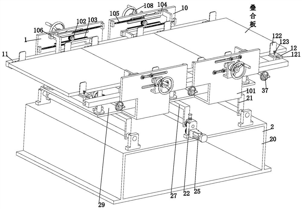
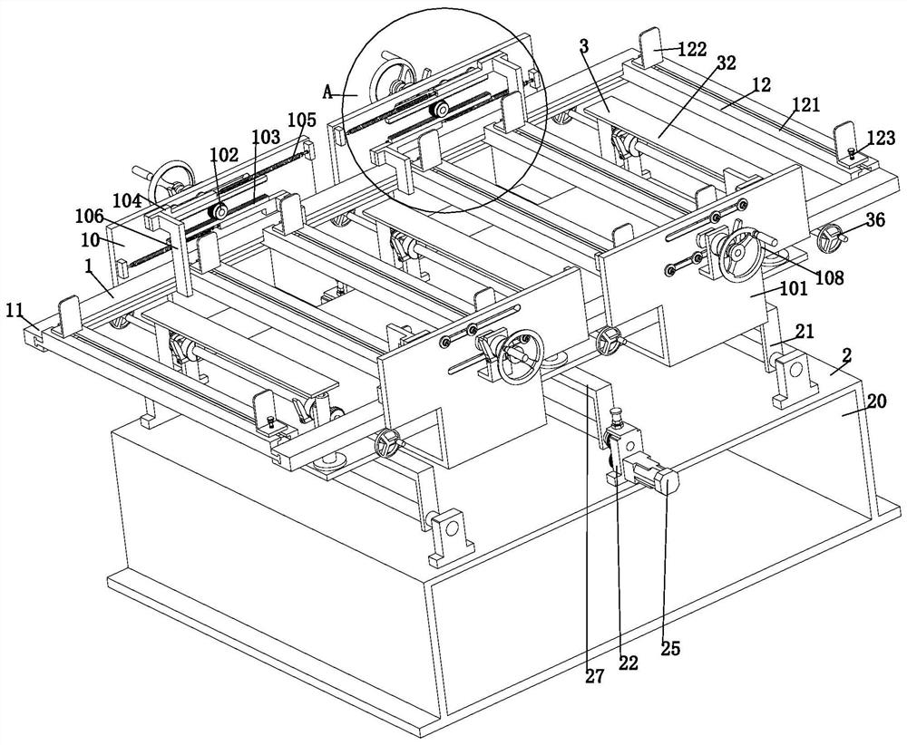
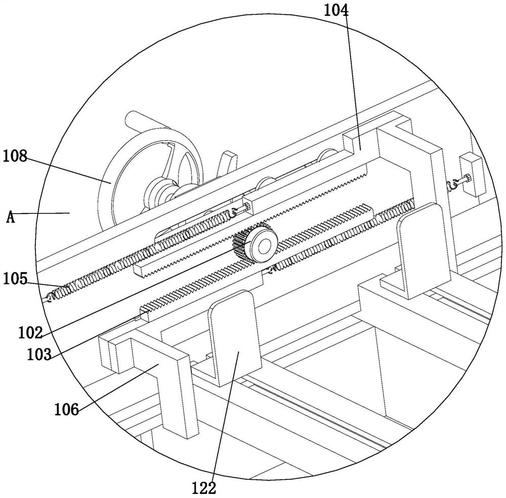
[0029] Such as Figure 1 to Figure 10 As shown, an assembled temporary support fixture for the installation of laminated panels includes a seam fastening mechanism 1, an indexing and indexing mechanism 2 and a jacking mechanism 3, and the indexing and indexing mechanism 2 is evenly provided with a jacking mechanism 3. The patchwork fastening mechanism 1 is installed on the indexing index mechanism 2, and the jacking mechanism 3 and the patchwork fastening mechanism 1 are both located directly above the indexing indexing mechanism 2, wherein:

[0030] The seam fastening mechanism 1 includes a fastening unit 10, a directional sliding guide rail 11 and a moving clamping unit 12; the fastening unit 10 is uniformly installed on the indexing index mechani...


PUM


Abstract

The invention provides a temporary supporting clamp for installation of an assembling type laminated slab. The supporting clamp comprises a splicing seam fastening mechanism, an indexing transpositionmechanism and jacking mechanisms, the jacking mechanisms are evenly arranged on the indexing transposition mechanism, the splicing seam fastening mechanism is installed on the indexing transpositionmechanism, and the jacking mechanisms and the splicing seam fastening mechanism are positioned right above the indexing transposition mechanism. The supporting clamp can solve the problems that, at present, after the laminated slab is hoisted, a concrete layer needs to be poured at the splicing seam of laminated slabs to enable the laminated slabs to work integrally as a whole but a steel pipe supporting frame is erected through a traditional supporting method to support the laminated slabs before pouring, the process of the mode is complicated, and uniform horizontal position height adjustment of the bottom faces of laminated slabs with different thicknesses cannot be conveniently carried out to reduced gaps between the laminated slabs, so slurry leakage can be caused by enlarged gaps between contact surfaces of the laminated slabs and laminated slabs with special inclination angles cannot be supported and clamped.

Description

technical field [0001] The invention relates to the technical field of an assembly-type composite panel installation fixture, in particular to an assembly-type composite panel installation temporary support fixture. Background technique [0002] With the rapid development of society, the housing industry in our country is also developing rapidly. Due to the outstanding advantages of saving scaffolding and formwork, convenient and fast construction, and good integrity, laminated panels are more and more used in various prefabricated or cast-in-place reinforced concrete structures; [0003] At present, after the laminated slab is hoisted, it is necessary to pour a concrete layer at the joint between the two laminated slabs to combine them into a whole and work together; but before pouring, the traditional support method is used to set up a steel pipe support frame to support the laminated slab , the process of this method is cumbersome, and it is not convenient to adjust the ...

Claims


Application Information

Patent Timeline
Patent Type & Authority Applications(China)
IPC IPC(8): E04G21/16
CPCE04G21/167
Inventor 吴传江
Owner 深圳市广弘盛工程建设有限公司
Learn More