A deicing device for photoelectric cables in winter

A technology for optoelectronic cables and equipment, applied in the field of deicing equipment for optoelectronic cables in winter, can solve the problems of collapsed optoelectronic cable towers, high optoelectronic cables, easy frostbite, etc., and achieve the effect of avoiding re-icing

Active Publication Date: 2021-08-06
嘉兴奥锶特光电科技有限公司
View PDF4 Cites 0 Cited by
  • Summary
  • Abstract
  • Description
  • Claims
  • Application Information

AI Technical Summary

Problems solved by technology

In winter, due to the low temperature, many photoelectric cables will freeze, and when it snows in winter, snow will also accumulate on the photoelectric cables, and the snow accumulated on the photoelectric cables will freeze directly, which is difficult If it is removed, it will be firmly attached to the surface of the photoelectric cable, which will increase the weight of the photoelectric cable, cause the photoelectric cable tower to overweight and collapse or the photoelectric cable will be broken, which will cause huge economic losses and dangers, while the traditional photoelectric cable Cable deicing is still generally done manually, but the photoelectric cables are generally high, and the temperature is low in winter. It is more dangerous for the staff to operate at high altitudes, and the length of the photoelectric cables is generally long, and the workload of deicing Larger, and when the temperature is low, it is easy to frostbite when working outdoors for a long time. Therefore, we propose a deicing device for photoelectric cables in winter

Method used


Image

  • A deicing device for photoelectric cables in winter
  • A deicing device for photoelectric cables in winter
  • A deicing device for photoelectric cables in winter

Examples


Embodiment Construction

[0023] The following will clearly and completely describe the technical solutions in the embodiments of the present invention with reference to the accompanying drawings in the embodiments of the present invention. Obviously, the described embodiments are only some, not all, embodiments of the present invention. Based on the embodiments of the present invention, all other embodiments obtained by persons of ordinary skill in the art without making creative efforts belong to the protection scope of the present invention.

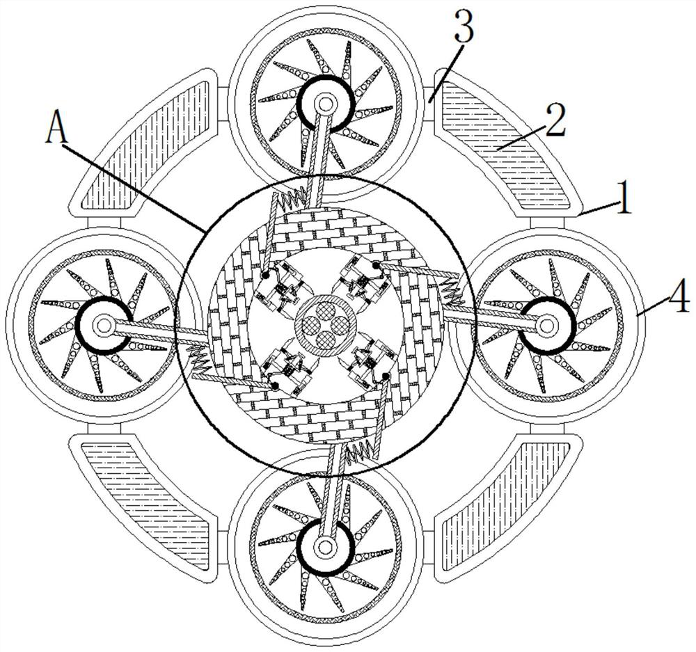
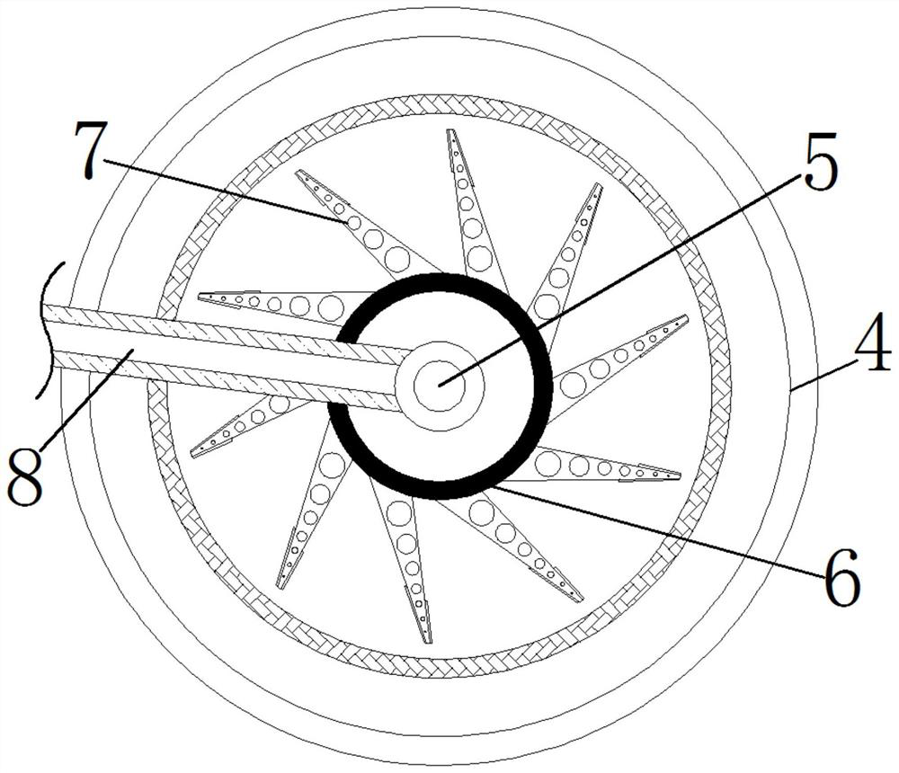
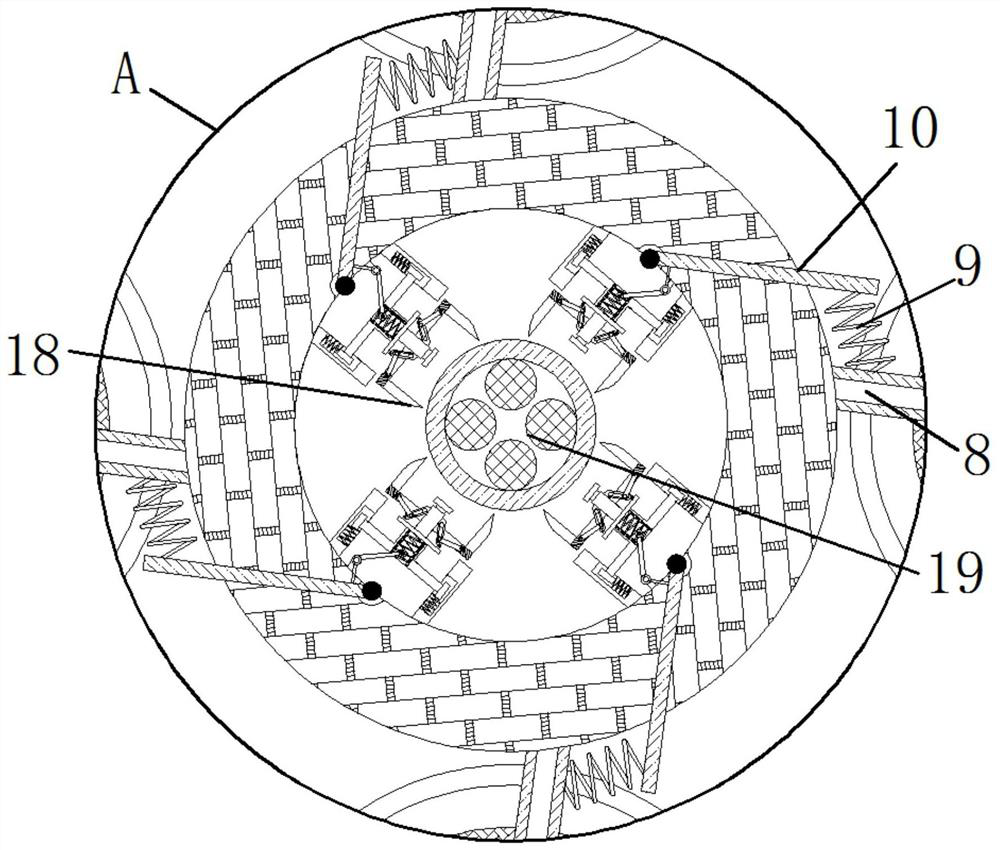
[0024] see Figure 1-6 , a deicing device for photoelectric cables in winter, including a device main body 1, an installation block 2 is arranged inside the device body 1, a connection block 3 is movably connected to the outside of the installation block 2, and the end of the connection block 3 is movable away from the installation block 2 Connected with an installation ring 4, the inside of the installation ring 4 is provided with a drive shaft 5, the outer s...


PUM


Abstract

The invention relates to the technical field of photoelectric cable deicing, and discloses a deicing device for photoelectric cables in winter, which includes a device main body, an installation block is arranged inside the device main body, and a connection block is movably connected to the outside of the installation block. The end away from the installation block is movably connected with an installation ring, and the inside of the installation ring is provided with a drive shaft, and the outside of the drive shaft is movably connected with a salt storage ring, and the outside of the salt storage ring is movably connected with a salt outlet pipeline, and the drive The outer side of the shaft center is movably connected with a shaft rod. The deicing equipment for photoelectric cables in winter synchronously drives the salt storage ring to start rotating through the rotation of the drive axis. The surface of the main body of the photoelectric cable makes it easier and quicker for the deicing knife to deice the main body of the photoelectric cable. After deicing the main body of the photoelectric cable, the spilled industrial salt also prevents the main body of the photoelectric cable from freezing again.

Description

technical field [0001] The invention relates to the technical field of photoelectric cable deicing, in particular to a deicing device for photoelectric cables in winter. Background technique [0002] Due to the development of industry, the amount of information required by users has exploded exponentially. This exponentially increasing amount of information conveyed through communication networks has led to the advent of fiber-to-the-home era, in which optical cables will reach the interior of buildings to greatly increase the flow of information. In winter, due to the low temperature, many photoelectric cables will freeze, and when it snows in winter, snow will also accumulate on the photoelectric cables, and the snow accumulated on the photoelectric cables will directly freeze, which is difficult Remove, firmly attached to the surface of the photoelectric cable, which will increase the weight of the photoelectric cable, cause the photoelectric cable tower to collapse due ...

Claims


Application Information

Patent Timeline
Patent Type & Authority Patents(China)
IPC IPC(8): H02G7/16H02G1/02
CPCH02G1/02H02G7/16
Inventor 陈建红
Owner 嘉兴奥锶特光电科技有限公司
Why Eureka
Try Eureka