Locking and unlocking control method and system

A control method and control system technology, applied in the field of new energy vehicles, can solve problems such as equipment problems that cannot be found, low success rate of unlocking, and failure of unlocking, so as to achieve fast and effective unlocking and replacement, and improve the success rate of unlocking , Complete action and correct effect

Active Publication Date: 2020-11-20
ZHEJIANG JIZHI NEW ENERGY AUTOMOBILE TECH CO LTD +1
View PDF5 Cites 0 Cited by
  • Summary
  • Abstract
  • Description
  • Claims
  • Application Information

AI Technical Summary

Problems solved by technology

[0004] At present, there are some technical problems in the power exchange equipment of the existing power exchange stations on the market, which lead to a low success rate of unlocking and unlocking. The specific technical problems are as follows:
[0005] (1) Unsuccessful unlocking: The unlocking device failed to completely locate

Method used


Image

  • Locking and unlocking control method and system
  • Locking and unlocking control method and system

Examples


Embodiment 1

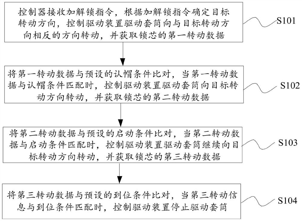
[0048] combine figure 1 As shown, the present embodiment 1 provides a locking and unlocking control method, which is applied to the locking and unlocking control system. The locking and unlocking control system includes a sleeve, a driving device, a lock cylinder, a lock body and a controller, and the lock cylinder is arranged in the lock body. The sleeve is set on the lock cylinder, the driving device is connected with the sleeve, the controller is connected with the driving device, and the sleeve can drive the lock cylinder to rotate relative to the lock body under the drive of the driving device, so as to realize locking or unlocking. The method includes :

[0049] Step S101: The controller receives the unlocking instruction, determines the target rotation direction according to the unlocking instruction, controls the driving device to drive the sleeve to rotate in the opposite direction to the target rotation direction, and acquires the first rotation data of the lock cylind...

Embodiment 2

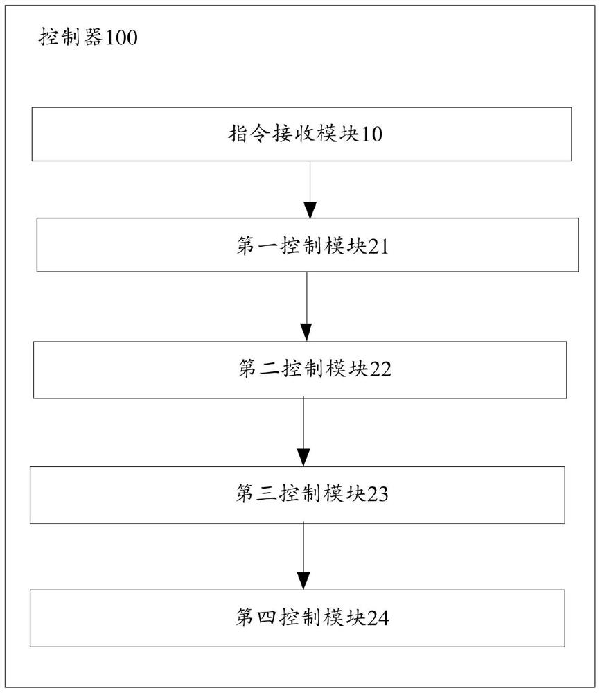
[0075] combine figure 2 As shown, the present embodiment 2 provides a locking and unlocking control system, the locking and unlocking control system includes a sleeve, a driving device, a lock cylinder, a lock body and a controller 100, the lock cylinder is set in the lock body, and the sleeve is set in the lock cylinder Above, the drive device is connected to the sleeve, the controller 100 is connected to the drive device, and the sleeve can drive the lock cylinder to rotate relative to the lock body under the drive of the drive device to realize locking or unlocking. It is characterized in that the controller 100 includes :

[0076] The command receiving module 10 is used to receive the locking and unlocking command, and determine the target rotation direction according to the locking and unlocking command,

[0077] The first control module 21 is configured to control the drive device to drive the sleeve to rotate in a direction opposite to the target rotation direction af...


PUM


Abstract

In order to improve s success rate of locking and unlocking, the invention provides a locking and unlocking control method and system. The locking and unlocking control method comprises the steps thata controller receives a locking and unlocking instruction, determines a target rotating direction according to the locking and unlocking instruction, makes a driving device drive a sleeve to rotate in the direction opposite to the target rotating direction, and obtains first rotating data of a lock cylinder; the first rotation data is compared with a preset cap recognition condition, and when thefirst rotation data is matched with the cap recognition condition, a driving device is controlled to drive the sleeve to rotate towards a target rotation direction, and second rotation data of the lock cylinder is acquired; the second rotation data is compared with a preset starting condition, and when the second rotation data is matched with the starting condition, the driving device is controlled to drive the sleeve to continue to rotate in the target rotation direction, and third rotation data of the lock cylinder is obtained; and the third rotation data is compared with a preset in-placecondition, and when third rotation information is matched with the in-place condition, the driving device is controlled to stop driving the sleeve.

Description

technical field [0001] The invention relates to the field of new energy vehicles, in particular to an unlocking and unlocking control method and system. Background technique [0002] The charging speed of electric vehicles is limited by battery fast charging technology and the popularity of charging piles. At present, ordinary power batteries have a relatively short battery life, while fast charging batteries need at least 1 hour of charging speed, and the cost is high. The popularity of charging piles It has not yet reached the level that electric vehicles can be charged anytime, anywhere. Therefore, a power station that can quickly replace the power battery and the body came into being. [0003] The purpose of changing the power station is to solve the above problems, so that the electric car can be replaced with a fully charged battery as quickly and conveniently as a gasoline car going to a gas station, without waiting for charging time, which is convenient and time-sav...

Claims


Application Information

Patent Timeline
IPC IPC(8): B60L53/80
CPCB60L53/80Y02T10/70Y02T10/7072
Inventor 王亚星石虎董林林杨全凯卢业林王志海韩磊
Owner ZHEJIANG JIZHI NEW ENERGY AUTOMOBILE TECH CO LTD
Why Eureka
Try Eureka