Eureka AIR delivers breakthrough ideas for toughest innovation challenges, trusted by R&D personnel around the world.

The transmission device of flapping and torsion combined motion of bionic flapping wing for micro air vehicle

A micro-aircraft and transmission technology, applied in aircraft, transportation and packaging, motor vehicles, etc., can solve problems such as difficulty in hovering or vertical take-off and landing, complex structure, low aerodynamic efficiency, etc., to achieve improved lift and simple operation Convenience and drag reduction effect

Active Publication Date: 2022-05-10
BEIJING INSTITUTE OF TECHNOLOGYGY
View PDF6 Cites 0 Cited by
  • Summary
  • Abstract
  • Description
  • Claims
  • Application Information

AI Technical Summary

Problems solved by technology

These three types of aircraft have their own advantages and disadvantages. To put it simply, fixed-wing aircraft has the traditional advantages of high-speed flight, but it is difficult to achieve hovering or vertical take-off and landing; The torque leads to a more complex structure, and there are also disadvantages of low aerodynamic efficiency at low Reynolds numbers

Method used


Image

  • The transmission device of flapping and torsion combined motion of bionic flapping wing for micro air vehicle
  • The transmission device of flapping and torsion combined motion of bionic flapping wing for micro air vehicle
  • The transmission device of flapping and torsion combined motion of bionic flapping wing for micro air vehicle

Examples


Embodiment 1

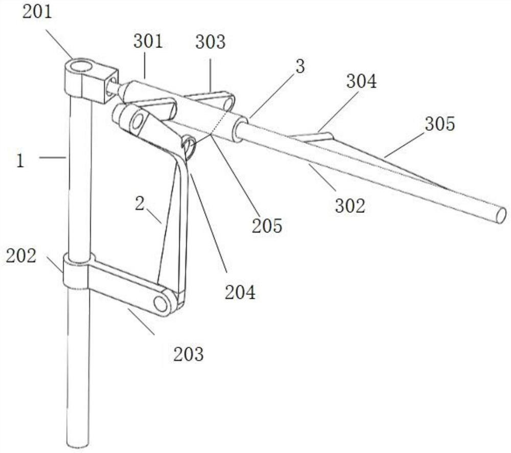
[0032] Such as figure 1 As shown, the bionic flapping wing flapping and twisting combined motion transmission device disclosed in this embodiment includes a support rod 1 , a transmission mechanism 2 , and a flapping wing main structure 3 .

[0033] Such as figure 1 As shown, the transmission mechanism includes an upper sleeve 201, a lower sleeve 202, a drive rod 203, a Γ-shaped connecting rod 204, and a limit rope 205; Beam 302, flapping wing main rib 303, flapping wing sub-beam 304, wing membrane 305.

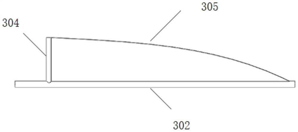
[0034] Such as figure 2 As shown, the wing includes a flapping wing outer spar 302 , a flapping wing sub-spar 304 , and a wing membrane 305 , wherein the flapping wing membrane 305 is bonded to the flapping wing outer spar 302 and the flapping wing sub-spar 304 .

[0035] The support rod 1 is arranged vertically, and the upper casing 201 is fixed on the top of the support rod 1, and can be used for a flapping rotorcraft through a bearing.

[0036] The lower bushing 202 i...


PUM


Abstract

The invention discloses a transmission device for combined movement of bionic flapping wings flapping and torsion for a micro-aircraft, belonging to the field of aircraft design. The invention includes a support rod, a transmission mechanism and a flapping wing main structure. The support rod is arranged vertically, its bottom is fixedly connected to the fuselage of the micro-aircraft, and its middle and top are respectively connected with the transmission mechanism and the main beam of the flapping wing. The transmission mechanism includes an upper sleeve, a lower sleeve, a drive rod, a Γ-shaped connecting rod and a limit rope; the main structure of the flapping wing includes the main beam of the flapping wing, the outer beam of the flapping wing, the main rib of the flapping wing, the sub-beam of the flapping wing and the wing membrane. The technical problems that can be solved by the present invention are: (1) effectively reduce the resistance when the wing is shot up while ensuring that the lift force is at the maximum value; (2) the flapping wing can be adjusted by adjusting the length of the limit rope; The twisting angle has the advantages of simple and convenient operation; (3) The resistance in the up-shooting stage is reduced, and the resistance in the down-shooting stage is not significantly different from that of traditional flapping wings, which has the advantage of high energy utilization.

Description

technical field [0001] The invention relates to a transmission device for combined movement of bionic flapping wings flapping and torsion for micro-aircraft, and belongs to the field of aircraft design. Background technique [0002] The micro air vehicle is small in size and easy to carry, and has good maneuverability and concealment. Therefore, MAVs are suitable for completing tasks such as exploration, reconnaissance, and rescue in narrow spaces and harsh environments. It is precisely because of the application requirements and vacancies of micro air vehicles under special conditions that micro air vehicles have become a research hotspot in the field of aviation in the past two decades. wing aircraft. These three types of aircraft have their own advantages and disadvantages. To put it simply, fixed-wing aircraft has the traditional advantages of high-speed flight, but it is difficult to achieve hovering or vertical take-off and landing; rotorcraft can achieve vertical ta...

Claims


Application Information

Patent Timeline
Patent Type & Authority Patents(China)
IPC IPC(8): B64C33/02B64C33/00
CPCB64C33/02B64C33/00
Inventor 贺媛媛赵辛敉郭士钧韩慧谢浩然
Owner BEIJING INSTITUTE OF TECHNOLOGYGY
Why Eureka
Eureka Blog
Learn More