
Lifting single bodies for vertical landing gear with fixed wings

A vertical take-off and landing, lift unit technology, applied in vertical take-off and landing aircraft, transportation and packaging, aircraft and other directions, can solve the problems of insufficient concentration of high-speed airflow, long blowing distance, and reduced lift.

Active Publication Date: 2015-07-22
HARBIN ENG UNIV
View PDF9 Cites 4 Cited by
  • Summary
  • Abstract
  • Description
  • Claims
  • Application Information

AI Technical Summary

Problems solved by technology

[0007] The disadvantages of the above structure are: the narrow and long semi-wind tunnel structure without a roof and the circular outlet of the axial flow fan will inevitably lead to a limited area swept by the high-speed airflow discharged, while the fixed wingspan is wide and extended, which leads to The high-speed airflow blowing over the fixed wing is not concentrated enough, and the blowing stroke is long. The wings arranged at the rear are in the airflow disturbed by the front, and the lift will drop sharply; thus, the average lift per unit area of ​​the wing will still not be very high.

Method used


Image

  • Lifting single bodies for vertical landing gear with fixed wings
  • Lifting single bodies for vertical landing gear with fixed wings
  • Lifting single bodies for vertical landing gear with fixed wings

Examples


Embodiment Construction

[0020] Preferred embodiments of the present invention are given below and described in conjunction with the accompanying drawings.

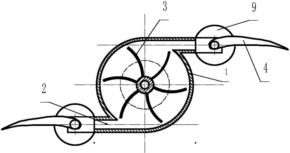
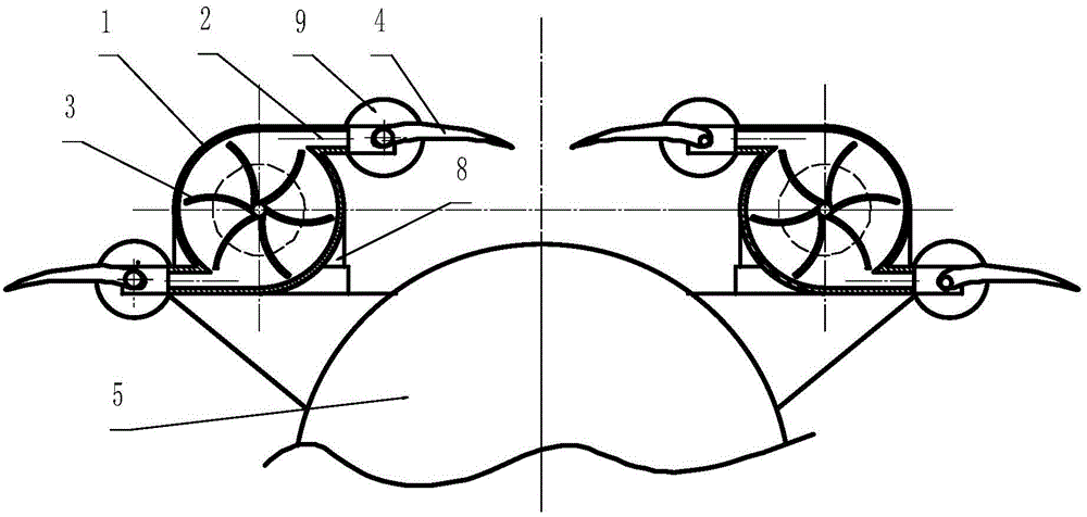
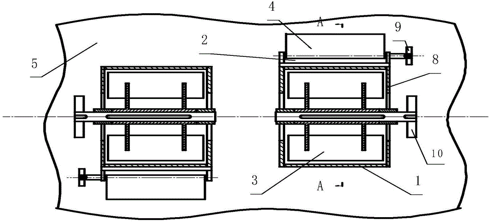
[0021] Such as figure 1 As shown, a lift unit of a vertical landing gear with a fixed wing includes a cylindrical body 1, an air outlet 2, a rotor 3, a wing 4, a carrier 5, a wing shaft 6, an end plate 8, a wing drive wheel 9 and rotor drive wheel 10; among them, the cylindrical barrel 1 used as the casing of the centrifugal fan is fixed with end plates 8 with circular air inlet holes at both ends; the rotor 3 with backward curved blades is fixed by means of solid The bearing seat and the rotor driving wheel 10 installed on the axis of the end plate 8 rotate in the cylindrical shell 1; the highest position and the lowest position in the cylindrical shell 1 are each equipped with a rectangular shell as the air outlet of the centrifugal fan 2. The long side of the rectangular section is along the generatrix direction of the cylindrical cylinder 1,...


PUM


Abstract

The invention discloses a vertical landing gear with fixed wings. The landing gear comprises two lift single bodies adopting the same structures and arranged in a parallel or coaxial-line manner, wherein each lift single body is characterized in that two attack-angle-adjustable fixed wings are mounted on each lift single body, and the high-speed airflow for generating the lift is from a high-speed rotary centrifugal fan, the wing-span direction of the fixed wings and the axial direction of the centrifugal fan are consistent, and the leading edges of the wings are positioned at the uppermost position and the lowest position of the cross section of the centrifugal fan as well as at strip-shaped exhaust outlets stretching in the tangential direction. The vertical landing gear has the benefits that the high-speed airflow blowing the wings is centralized, so that the average lift on unit area of the wings is improved.

Description

technical field [0001] A vertical take-off and landing device with a fixed wing, characterized by a fixed wing with an adjustable angle of attack, but the high-speed airflow that generates lift comes from a high-speed rotating centrifugal fan. It belongs to the field of aircraft capable of vertical takeoff or landing. Background technique [0002] The research and production of vertical take-off and landing aircraft has achieved amazing results, and it has shown its talents in the military field where cutting-edge technologies gather, but it has not stopped people's exploration of new vertical take-off and landing devices. [0003] Relevant documents have pointed out that: the quality factor of the existing rotary-wing helicopter rotor is low, and the energy loss is relatively large. In fact, since multiple rotors are radially connected to the main shaft, the speed of each point in the span direction of each rotor is linearly distributed starting from zero, and the airfoil ...

Claims


Application Information

Patent Timeline
Patent Type & Authority Applications(China)
IPC IPC(8): B64C29/00
Inventor 李鸿郑全逸
Owner HARBIN ENG UNIV
Learn More