
Novel agricultural machinery irrigator

A technology for agricultural machinery and irrigators, which is applied in the field of agriculture and can solve the problems of slow start and rotation of agricultural irrigators

Inactive Publication Date: 2020-11-27
北京极佳味道酒店管理有限公司
View PDF7 Cites 0 Cited by
  • Summary
  • Abstract
  • Description
  • Claims
  • Application Information

AI Technical Summary

Problems solved by technology

[0003] It is well known that there are many nutrients in the water of canals and rivers, and there is often a large gap between the shaft of the agricultural irrigator and the outer pipe for fast rotation, so that water will accumulate between the shaft and the outer pipe after use, and it has not been used for a long time Moss will grow between the rotating shaft and the outer tube, and the growing moss will easily fill the gap between the rotating shaft and the outer tube, which will cause the agricultural irrigator to turn extremely slowly when it is used again.

Method used


Image

  • Novel agricultural machinery irrigator
  • Novel agricultural machinery irrigator
  • Novel agricultural machinery irrigator

Examples


Embodiment 1

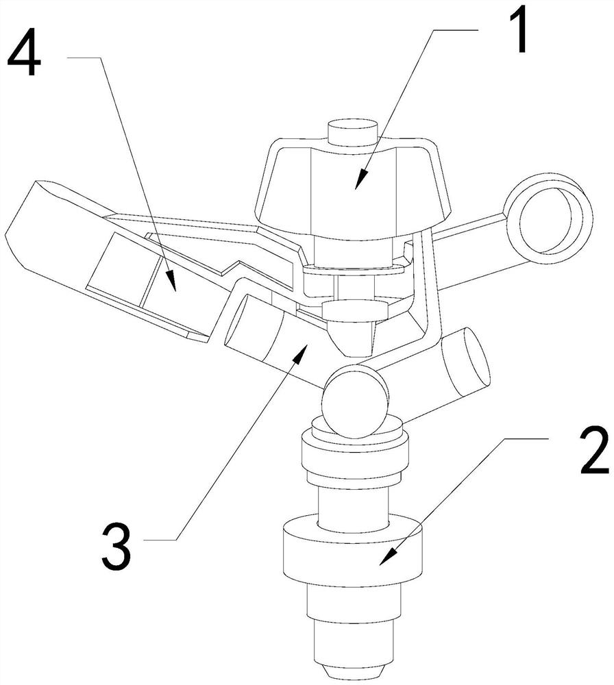
[0026] For example figure 1 -example Figure 5 Shown:

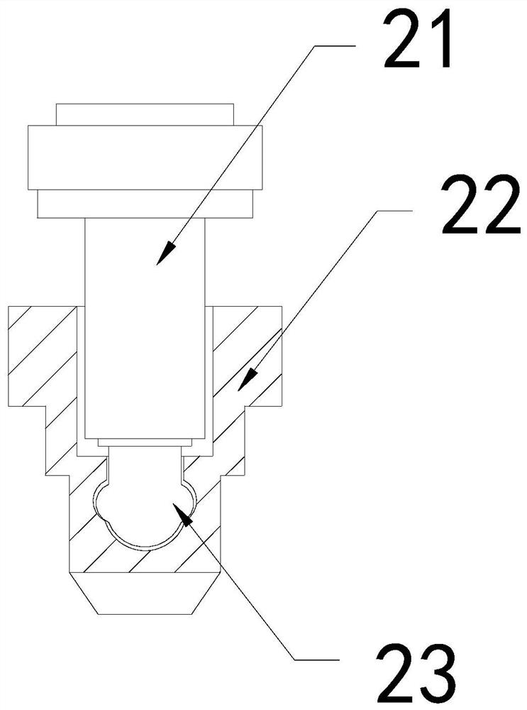
[0027] The invention provides a new type of agricultural machinery irrigator, the structure of which includes a linkage head 1, a turret 2, a water spray pipe 3, and a force plate 4, the turret 2 is installed at the bottom of the linkage head 1, and the force The plate 4 and the linkage head 1 are an integrated structure, and the water spray pipe 3 is embedded in the left side of the linkage head 1; The movable block 23 is an integrated structure, and the movable block 23 is movably engaged with the inside of the outer tube 22 .

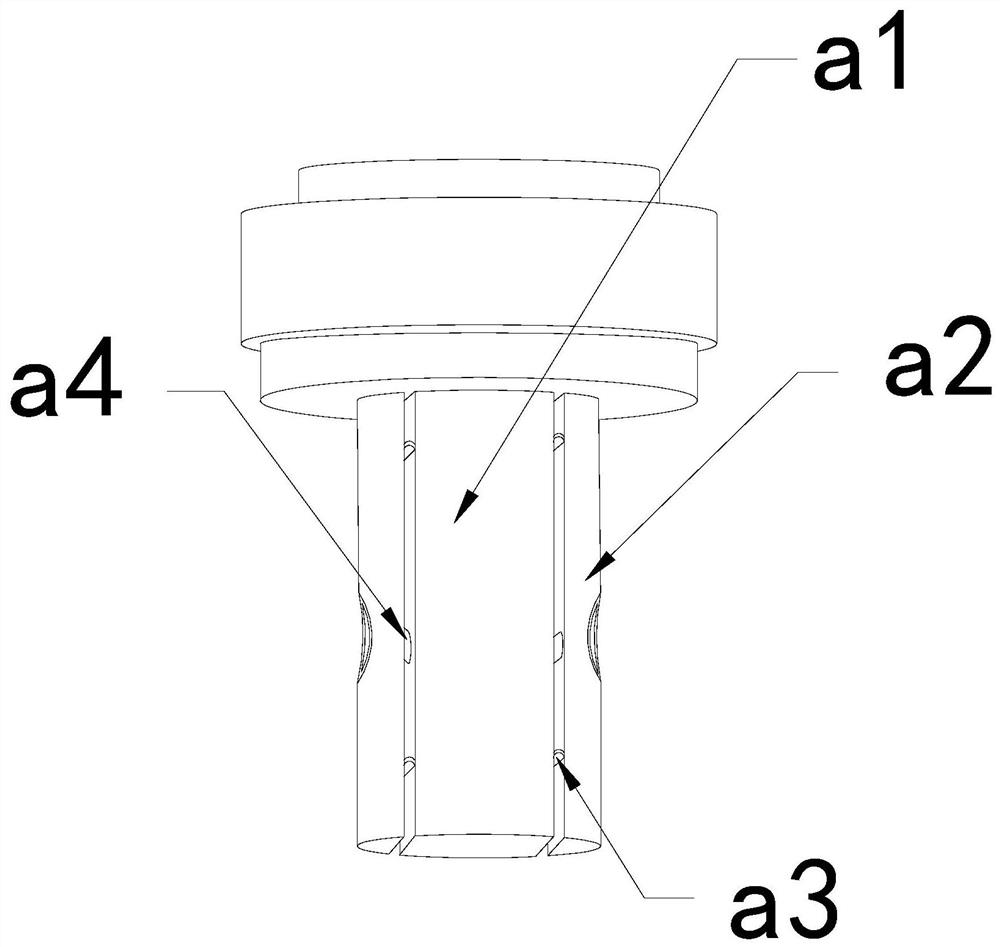
[0028] Wherein, the rotating shaft 21 includes a central solid rod a1, an outer expansion plate a2, an elastic piece a3, and a water guide pipe a4. The outer expansion plate a2 is connected with the middle solid bar a1 through the elastic plate a3, and the water guide a4 is installed on the outer expansion plate. Between a2 and the middle solid rod a1, the outer expansion plate a2 is provided...

Embodiment 2

[0034] For example Image 6 -example Figure 8 Shown:

[0035] Wherein, the blocking mechanism a12 includes a take-out plate c1, an connecting plate c2, an elastic sheet c3, an inner ring c4, and the taking-out plate c1 is embedded and fixed on the outer surface of the connecting plate c2, and the connecting plate c2 and the inner ring c4 are movable. The elastic piece c3 is installed between the take-out plate c1 and the inner ring c4. There are four take-out plates c1, which are evenly distributed in a circular shape outside the inner ring c4. The extrusion generated by the output plate c1 can make the output plate c1 shrink inwardly.

[0036] Wherein, the take-out plate c1 includes a blocking plate c11, a water outlet c12, and a receiving plate c13, the blocking plate c11 is hingedly connected to the top of the receiving plate c13, and the water outlet c12 and the blocking plate c11 are an integrated structure, so There are four blocking plates c11, which are evenly dist...


PUM


Abstract

The invention discloses a novel agricultural machinery irrigator. The irrigator structurally comprises a linkage head, a rotating frame, a water spraying pipe and a stress plate, wherein the rotatingframe is mounted at the bottom of the linkage head, the stress plate and the linkage head are of an integrated structure, the water spraying pipe is fixedly embedded in the left side of the linkage head, when a movable block stops rotating, an outer expansion plate can be pushed to be tightly attached to the inner wall of an outer pipe through an elastic sheet; therefore, water between the outer pipe and the outer expansion plate can be discharged into a middle fixing rod through the water guide pipe; moss and water on the upper surface of the lifting block can be thrown out towards the two sides through throwing force generated by rotation of the rotating shaft; the situation that moss grows due to the fact that moisture stays between the rotating shaft and the outer pipe for a long timeis effectively avoided; water and moss in the middle fixing rod generate outward pushing force on the blocking mechanism, a groove in the upper surface of a take-out plate can take out the water and the moss, water flow outside the middle fixing rod carries the moss to pass through the take-out plate, and then a blocking plate can block the moss squeezed by the water.

Description

technical field [0001] The invention relates to the field of agriculture, in particular to a novel agricultural machinery irrigator. Background technique [0002] The agricultural irrigator is mainly used for spraying and irrigating the crops. Generally, it needs to be connected to the water pipe. By spraying the water flow of the water pipe upward at high speed, the water flow can be obliquely sprayed out of the impact barrier plate by the impact pipe, so that the agricultural The irrigator can be rotated so that the water flow can be thrown around, and most of the water sprayed from the water pipe connected to the agricultural irrigator comes from water areas such as canals and rivers, and is widely used in large-scale agricultural planting industries. Based on the above description, the inventor It is found that an existing novel agricultural machine irrigator mainly has the following deficiencies, such as: [0003] It is well known that there are many nutrients in the w...

Claims


Application Information

Patent Timeline
Patent Type & Authority Applications(China)
IPC IPC(8): A01G25/02B05B15/555
CPCA01G25/02B05B15/555Y02A40/22
Inventor 黄佳彬
Owner 北京极佳味道酒店管理有限公司
Learn More