Cylindrical town sewage treatment equipment

A technology of urban sewage and treatment equipment, which is applied in the field of urban sewage treatment and resource utilization, and can solve the problem of decreased permeability of the filter layer to sewage.

Inactive Publication Date: 2021-11-02
万闽
View PDF0 Cites 0 Cited by
  • Summary
  • Abstract
  • Description
  • Claims
  • Application Information

AI Technical Summary

Problems solved by technology

[0003] If the moss spores growing on the inner wall of the sewage pipe connected to the sewage treatment inlet follow the sewage into the sewage treatment unit, the small moss spores will be discharged downward through the filter layer. If the moss spores follow the water and hang on the filter layer At the bottom of the filter layer, it will grow at the bottom of the filter layer under the action of sewage with high nutrient content, and long-term accumulation will reduce the permeability of the filter layer to sewage

Method used


Image

  • Cylindrical town sewage treatment equipment
  • Cylindrical town sewage treatment equipment
  • Cylindrical town sewage treatment equipment

Examples


Embodiment 1

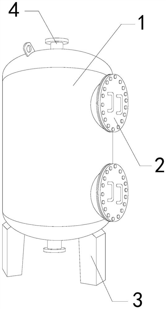
[0028] For example figure 1 -example Figure 5 Shown:

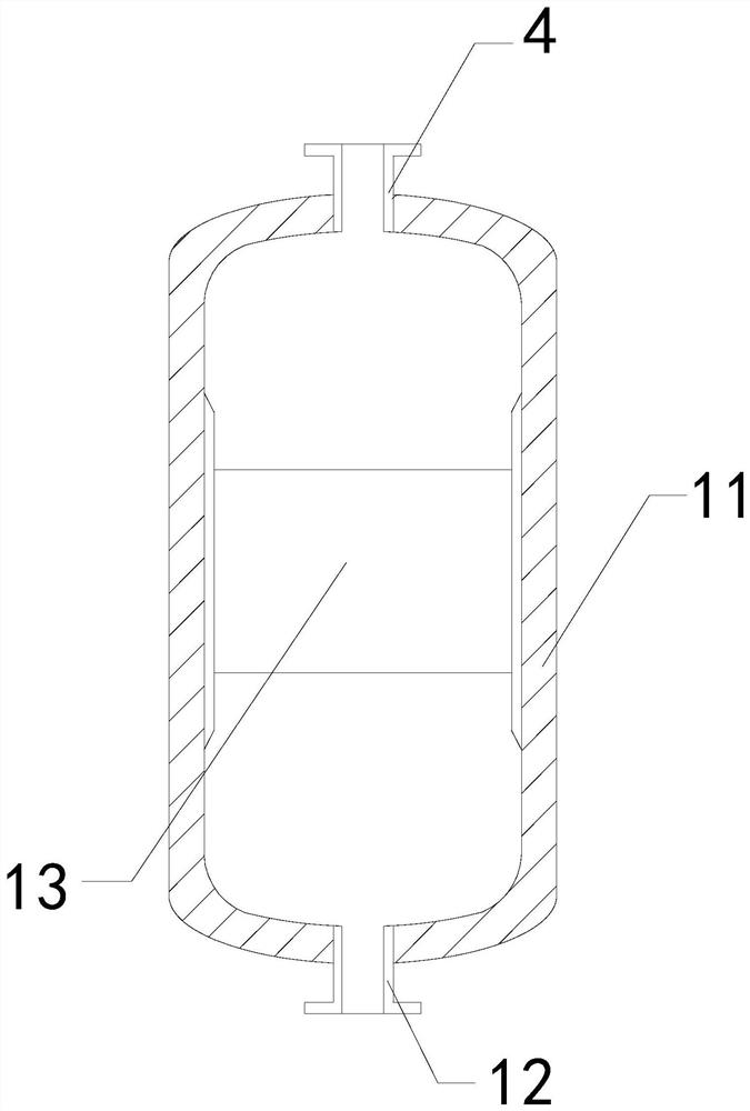
[0029] The invention provides a cylindrical urban sewage treatment equipment, the structure of which includes a tank body 1, an observation port 2, a base bracket 3, and a sewage inlet 4. The observation port 2 is installed on the side of the tank body 1, and the The sewage inlet 4 is embedded in the upper end of the tank body 1, and the bottom of the tank body 1 is welded to the upper end of the base bracket 3; The drain port 12 is fixed at the lower end of the outer frame 11 , and the filter layer 13 is fixed between the inner walls of the outer frame 11 .

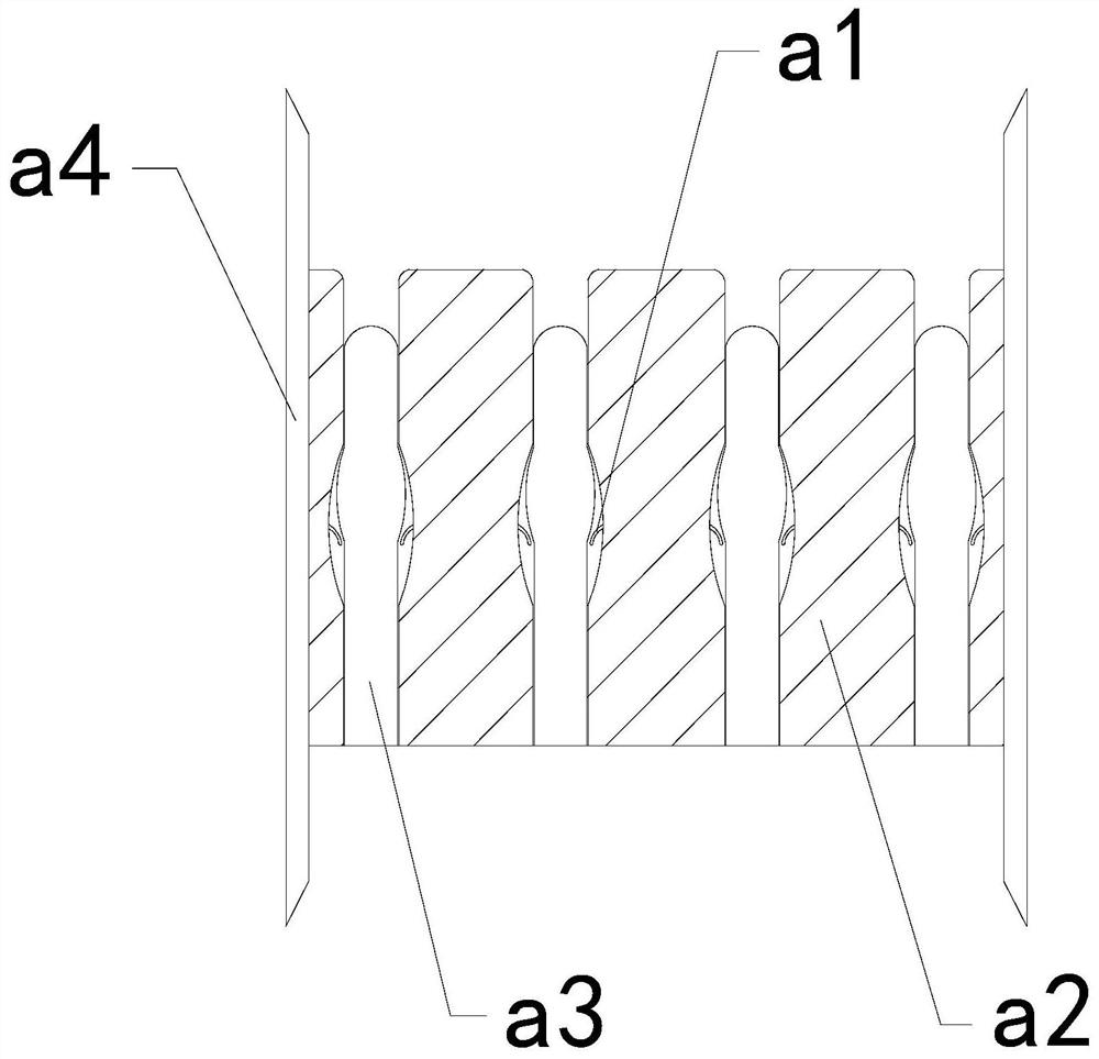
[0030] Wherein, the filter layer 13 includes a rebound piece a1, a purification block a2, a sliding bar a3, and an connecting plate a4, the rebounding piece a1 is connected to the inner wall of the purification block a2, and the purification block a2 is installed on two connecting plates a4 Between the inner sides of the sliding rod a3 and the inside of the rebou...

Embodiment 2

[0036] For example Figure 6 -example Figure 9 Shown:

[0037]Wherein, the bearing block b3 includes an external frame b31, a bottom slide b32, a rebound bar b33, and a linkage block b34, the upper end of the bottom slide b32 is connected to the bottom of the linkage block b34, and the rebound bar b33 is installed on the linkage block Between b34 and the inner wall of the outer frame b31, the linkage block b34 is slidingly fitted with the inner side of the outer frame b31, and there are two linkage blocks b34, which are evenly symmetrical on the inner walls of the left and right sides of the outer frame b31 Distribution, through the inertial force generated by the mechanism sliding downwards and protruding, the bottom sliding plate b32 can slide and protrude downwards along the outer frame b31 under the cooperation of the linkage block b34, so that the bottom sliding plate b32 can shake off part of the moss.

[0038] Wherein, the bottom sliding plate b32 includes a top plat...


PUM


Abstract

The invention discloses cylindrical town sewage treatment equipment which structurally comprises a tank body, an observation opening, a base support and a sewage inlet, wherein the observation opening is formed in the side position of the tank body, the sewage inlet is fixedly embedded in the upper end position of the tank body, the bottom of the tank body is welded to the upper end of the base support, and a rebounding piece can push a lower sliding rod losing town sewage thrust to rapidly reset upwards along a purification block, so that a deformation piece can extrude the bottom of the purification block before being extruded and restored, the purification block can extrude a large amount of water flow, and moss at the bottom of the purification block can be scattered. Through inertia force generated when the lower sliding rod slides downwards along the purification block under the impact force of urban sewage, a bottom sliding plate can slide downwards and descend along an external frame under the cooperation of a linkage block, then through throwing force generated when the bottom sliding plate extends downwards, a bearing block can swing downwards along a top plate, and then moss at the bottom of the bottom sliding plate can be thrown off.

Description

technical field [0001] The invention relates to the technical field of urban sewage treatment and resource utilization, in particular to a cylindrical urban sewage treatment equipment. Background technique [0002] The cylindrical urban sewage processor is mainly used for the purification and treatment of urban sewage. The urban sewage is discharged into the interior of the cylindrical urban sewage processor through the sewage inlet, and then passed through the interior of the cylindrical urban sewage processor. The filter layer is used to filter the large particle pollutants inside the urban sewage, and finally the filtered sewage is discharged into the next process for further purification. Based on the above description, the inventors found that the existing cylindrical urban sewage The processing equipment mainly has the following deficiencies, such as: [0003] If the moss spores growing on the inner wall of the sewage pipe connected to the sewage treatment inlet follo...

Claims


Application Information

Patent Timeline
IPC IPC(8): B01D35/30B01D29/00B01D29/62C02F1/00
Inventor 万闽
Owner 万闽
Why Eureka
Try Eureka