

Scraping device for acupuncture and massage
A scraping and acupuncture technology, applied in the field of medical physiotherapy, can solve the problems of medical staff's workload, scraping oil flowing, scraping oil waste, etc., and achieve the effects of simple action, waste avoidance and simple operation.
- Summary
- Abstract
- Description
- Claims
- Application Information
AI Technical Summary
Problems solved by technology
Method used
Image

Examples
Embodiment 1
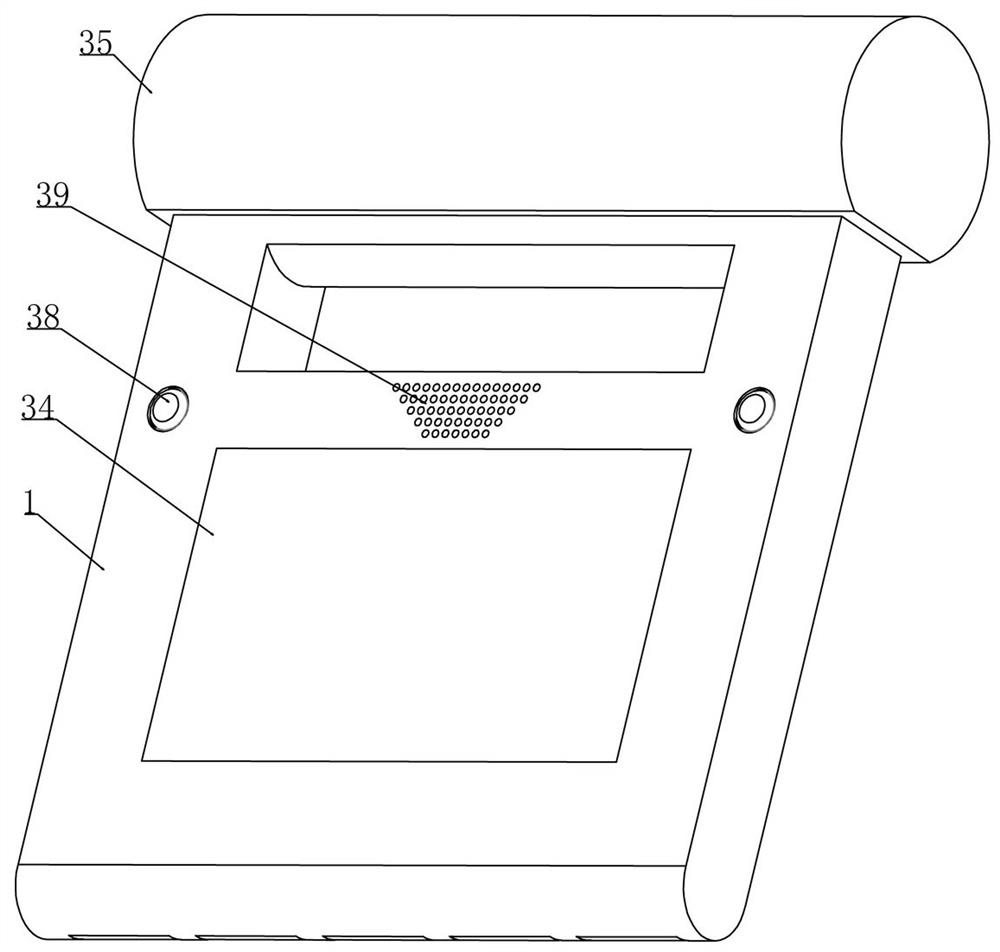
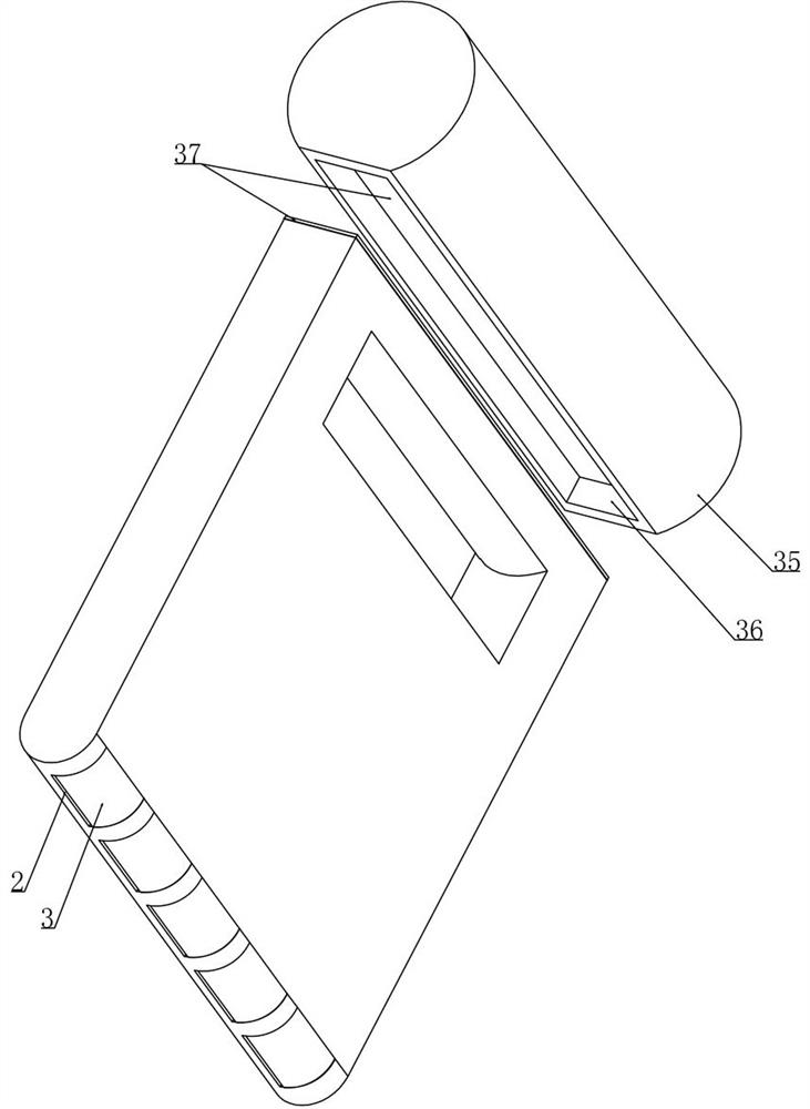
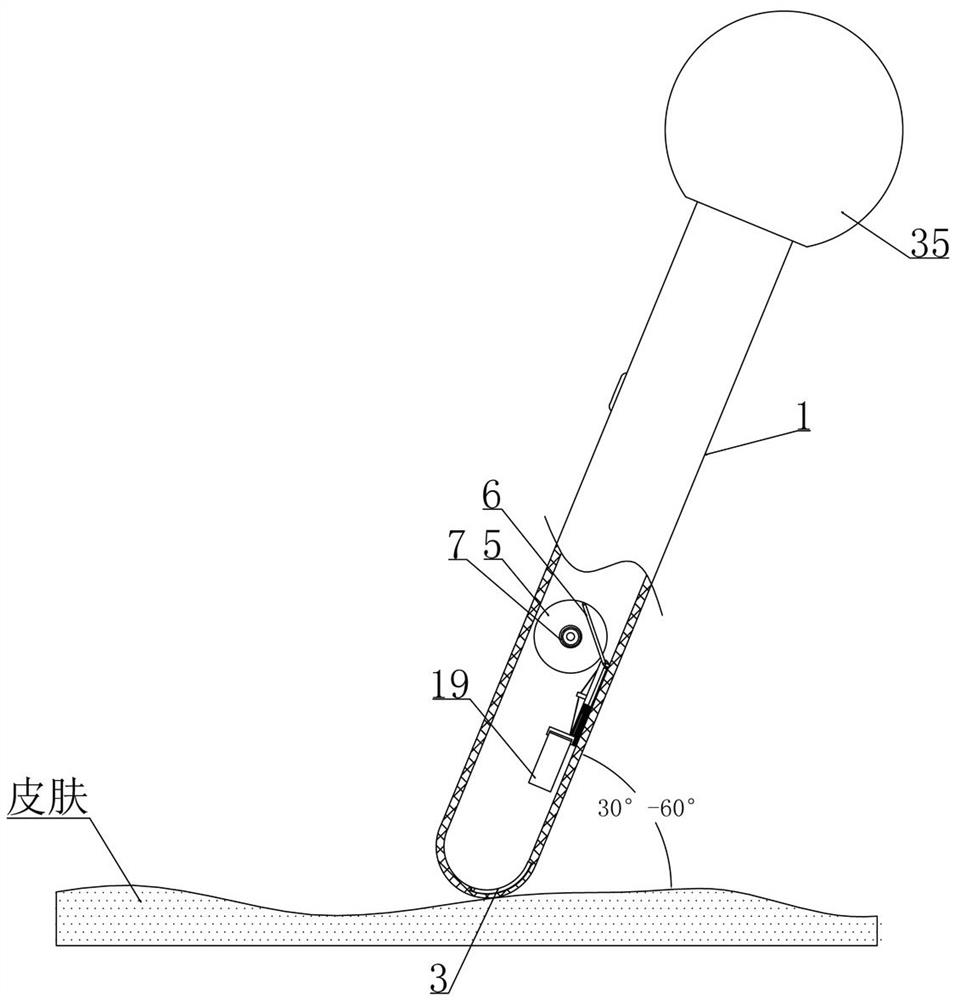
[0029] Embodiment 1, this program provides a scraping device for acupuncture and massage, the structure is as attached figure 1 As shown, the scraper 1 is included and the bottom of the scraper 1 is set in an arc shape (the arc part is in contact with the patient's body surface skin and realizes scraping and friction on the patient's body surface, and is set in an arc shape so that during the scraping process, the patient feel more comfortable), the improvement of this program is: as attached figure 2 As shown, a number of openings 2 are arranged at intervals in the arc-shaped part of the bottom of the scraper 1, and arc-shaped plates 3 are installed in the openings 2, as shown in the attached image 3 As shown, when performing scraping, the angle between the scraper 1 and the patient's surface skin is preferably in the range of 30°-60°, and 45° is the most common and suitable angle. The medical staff holds the scraper 1 on the patient's back from top to bottom. Scraping and...
Embodiment 2
[0034] Embodiment 2, on the basis of embodiment 1, as attached Figure 9 As shown, the transmission device includes drive plates 5 arranged at intervals in the scraper 1, and several drive plates 5 rotate coaxially, and a connecting rod 6 is installed on the drive plate 5 for eccentric rotation, and the other end of the connecting rod 6 is installed in rotation with the wiping frame 4. as attached Figure 8 As shown, the driving device includes a micromotor 11 fixed in the scraper 1 and the micromotor 11 drives a drive shaft 8 that is rotatably installed in the scraper 1. The transmission cylinder 9 and the inner wall of the drive shaft 8 and the outer wall of the transmission cylinder 9 are fixed with abutment plates 10 at intervals (the two abutment plates 10 are arranged symmetrically to each other), as attached Figure 16 shown;
[0035] as attached Figure 8 As shown, the drive cylinder 9 is driven by a belt drive with a gear set located in the scraper 1 and the gear set...
Embodiment 3
[0039] Embodiment 3, on the basis of embodiment 2, as attached Figure 9 , 10 As shown, the wiping frame 4 includes a slide bar 12 that is slidably installed with the inner side wall of the scraper 1 and is rotatably installed with the connecting rod 6, and a telescopic spring 14 is connected between the slide bar 12 and the mounting frame 13, as attached Figure 10 As shown, the upper end of the slide bar 12 is rotated and installed with a wire wheel 15 and a wire rope 16 is wound on the wire wheel 15. The wire wheel 15 rotates coaxially with a control gear 17 and the control gear 17 is meshed with a control gear system arranged on the inner wall of the scraper 1. 18. Initially, the control gear 17 and the control gear train 18 are in the meshing state and the wire rope 16 is wound on the wire wheel 15, and the telescopic spring 14 connected between the slide bar 12 and the mounting frame 13 is in a state of tension under the tension of the wire rope 16. In the compressed st...
PUM
 Abstract
Description
Claims
Application Information